Table of Contents
Advertisement
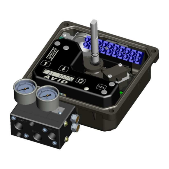
EaziCal II - Intrinsically Safe Valve Positioner
Tech-537
IOM:
Prepared By:
Peter Keating
Reviewed By:
Chris Irwin
This IOM contains confidential information and is issued in confidence on the condition that it be returned on demand and not be copied,
reproduced, disclosed to others or used in manufacture of the subject matter thereof without the written consent of Crane Co.
280N MIDLAND AVENUE, STE.258, SADDLE BROOK, NJ 07663 TEL: 201-794-7650 FAX: 201-794-0913
01/05/2018
Controls
OPERATING MANUAL
Revision: -
Date:
Drafting Work Order: 23142 ECN: -
10/25/2017
Date:
Approved By:
1/5/2018
Jason Moorehead
CRANE Co.
www.avidcontrols.com
TECH-537/ D.W.O. 23142
Date:
1/5/2018
Page 1 of 21
Advertisement
Table of Contents

Related Manuals for Avid Technology EaziCal II


Summary of Contents for Avid Technology EaziCal II
- Page 1 Controls EaziCal II - Intrinsically Safe Valve Positioner OPERATING MANUAL Revision: - Tech-537 IOM: Prepared By: Date: Drafting Work Order: 23142 ECN: - Peter Keating 10/25/2017 Reviewed By: Date: Approved By: Date: Chris Irwin 1/5/2018 Jason Moorehead 1/5/2018 This IOM contains confidential information and is issued in confidence on the condition that it be returned on demand and not be copied, reproduced, disclosed to others or used in manufacture of the subject matter thereof without the written consent of Crane Co.
- Page 2 Revision History Revision 01/05/2018 Initial release Locations Phone: (201) 794-7650 Europe Phone: 011-44-189-251-6277 South America Phone: + 55 11 2588-1400 Asia Phone: +65 676 858 00 CRANE Co. 280N MIDLAND AVENUE, STE.258, SADDLE BROOK, NJ 07663 TEL: 201-794-7650 FAX: 201-794-0913 www.avidcontrols.com 01/05/2018 TECH-537/ D.W.O.
-
Page 3: Table Of Contents
Table of Contents Introduction........................4 Product Certification ....................4 Warnings ......................... 4 Description ......................5 Principles of Operation .................... 5 Special Features ....................... 6 Order Guide ........................7 Definitions ........................8 Installation ........................8 Mounting ......................... 8 Calibration ......................10 Field Wiring ........................ -
Page 4: Introduction
This unit may be equipped with either two 3-wire switches or two 2-wire inductive sensors. Warnings WARNING: The aluminum housing Model EaziCal II Ex ia is at potential risk of ignition by impact or friction therefore, care must be taken into account during installation to avoid this problem. -
Page 5: Description
Mechanical, proximity & inductive proximity type. Principles of Operation The EaziCal II utilizes two keys for auto calibration and two keys for settings. This controls both Positioner and Position Transmitter with local LCD in conjunction with the Diagnostic / Fault LED. -
Page 6: Special Features
20mA with 4mA being 0% open and 20mA being 100% open. If the main section of the EaziCal II fails and so ceases to provide position updates to the Transmitter or the position sensor fails on the main section, so that the current valve position is unknown, the Transmitter will put out a current of 3.5mA or 21.5mA... -
Page 7: Order Guide
Order Guide Base Model AVID EaziCal II Positioner Housing material Aluminium Stainless Steel CF8M (316) Engineered resin Application Re-Transmission R High Flow and Re-Transmission Conduit Entry 2 1 x M20 5 1 x 3/4" NPT 8 1 x M25 B 2 x M20 (ATEX &... -
Page 8: Definitions
Definitions This symbol warns the user of possible danger. Failure to heed this warning may lead to personal injury or death and/or severe damage to equipment. This symbol identifies information about operating the equipment in a particular manner that may damage it or result in a system failure. - Page 9 Namur Shaft Namur Mounting Bracket Remove Mod Mount Bracket to expose Namur Shaft Namur Actuator Figure 2 Mounting for Shaft Option Namur Mount to Keystone 79U or MRP Actuators Pneumatic piping: Single Acting Actuator (Spring Return): For single acting actuators Outlet Port 2 is to be plugged. Outlet Port 1 is to be piped to the actuator inlet port that acts against the spring.
-
Page 10: Calibration
Figure 3 Standard Flow Manifold Figure 4 High Flow Manifold Calibration There are 3 auto calibrate modes (all modes auto calibrate the Transmitter) o Auto Calibration for 4mA to 20mA. o Calibration for Low current calibration other than 4mA. o Calibration for High current calibration other than 20mA. 4.3.1 Auto Calibration for 4mA to 20mA operation This is a two Key auto calibration that defines 4mA for the valve being fully closed and 20mA for valve being fully open. - Page 11 4.3.2 Auto Calibration for Low current Calibration other than 4mA (Split Range) The Low calibration refers to the input current value that drives the valve into the fail position. The Transmitter Function is being automatically calibrated during this procedure. First follow the procedure for the Auto Calibration Next set loop current to the desired value.
- Page 12 To enter Manual Calibration, Press the Key until MAN CAL is shown on the display will show FWGN xx. Repeatedly pressing the switch will cycle through what can be changed. FWGN xx RVGN xx DR ENABL or DR DISAB based upon what is set ZERO xx SPAN xx DIR ACTG or REV ACTG based upon what is set...
- Page 13 4.4.5 Span Position (SPAN XX) - Adjusts the electronic stop away from (increasing values) or towards (decreasing values) from the physical open position. 0 being nominally the position of the hard stop Span Zero and 100 about 15 degrees away from it Pressing DOWN Key reduces the span position of the valve away from the hard stop Pressing UP Key moves the span position closer to the hard stop.
- Page 14 4.4.10 Cancelling Calibration When the LCD displays “AUTO CAL” and you do not want to perform this operation. Do nothing. Within 15 seconds the function displayed is canceled and the LCD display reverts back to opening percentage “xx %” If starting an Auto Calibration by mistake. Wait 5 seconds and press again.
- Page 15 Before stroking the actuator, please ensure that the process is safe to do so and that all hands are kept away from the moving shaft / cams. Stroke the actuator to the opposite end of travel. Set the top EasiFix self-locking cam by pushing down and turning the EasiFix self-locking cam until the switch is activated.
- Page 16 Wiring Diagrams: Figure 6 - No Switch option Figure 7 - SPDT mechanical switches Figure 8 - SPDT T-Switch proximity switch Figure 9 - Namur Inductive proximity sensors Figure 11 – Ind. Prox Sensors (IFM IS5026) Figure 12 - Ind Prox Sensors (IFM IS50011/P&F NBB2-V3-E2-3G-3D) CRANE Co.
-
Page 17: Maintenance And Repair
Maintenance and Repair The positioner’s onboard filter should be replaced regularly or whenever it gets clogged. See diagram below for location of the filter. Note: the following instructions are for Standard Flow. For High Flow please contact the factory. Important: The positioner’s onboard filter is not a substitute for normal instrument air preparation. -
Page 18: Appendix
Appendix Appendix: A Intrinsically Safe wiring: Controlled Diagram CRANE Co. 280N MIDLAND AVENUE, STE.258, SADDLE BROOK, NJ 07663 TEL: 201-794-7650 FAX: 201-794-0913 www.avidcontrols.com 01/05/2018 TECH-537/ D.W.O. 23142 Page 18 of 21... - Page 19 TRANSDUCER ERROR When preforming an Auto Calibration if the LCD shows “TRANSDUCER ERROR” within 2 minutes. The transducer is not connected to the EaziCal II. UNABLE TO CLOSE When preforming an Auto Calibration and within 2 minutes the LCD displays “UNABLE TO CLOSE”.
- Page 20 Appendix: C Dimensions: CRANE Co. 280N MIDLAND AVENUE, STE.258, SADDLE BROOK, NJ 07663 TEL: 201-794-7650 FAX: 201-794-0913 www.avidcontrols.com 01/05/2018 TECH-537/ D.W.O. 23142 Page 20 of 21...
- Page 21 Appendix D: AVID EaziCal II - Quick Start Guide -AUTO CALIBRATION INSTRUCTIONS- PRESS AND RELEASE [SEL]. DISPLAY WILL SHOW 'AUTO CAL'. PRESS AUTO CAL WILL BEGIN WITH 4MA AS LOW CURRENT AND 20MA AS HIGH CURRENT. -SETTING LOW AND HIGH LOOP CURRENT- -LOW CURRENT- SET LOOP CURRENT TO IDLE VALUE.
Need help?
Do you have a question about the EaziCal II and is the answer not in the manual?
Questions and answers