Table of Contents
Advertisement
Quick Links
AVID
Contents
1
1.1
1.2
2
2.1
2.2
2.3
2.4
2.5
2.6
2.7
3
3.1
3.2
3.3
3.4
3.5
3.6
3.7
3.8
4
4.1
4.2
4.3
4.4
4.5
5
5.1
5.2
6
7
8
Appendices
B
Procedure to remove electronics
cover and electronic canister
C
Setting the transmitter output
fail current
www.cranecpe.com
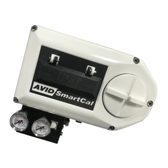
AVID SmartCal valve positioner
Installation & operating instructions
Installation and operating instructions for the AVID
SmartCal intelligent valve positioner
2
2
2
4
4
5
6
7
9
10
11
12
12
12
13
13
14
14
15
16
18
19
20
21
22
23
24
24
25
26
26
H
Control schematic for wiring of
intrinsically safe SmartCal for
27
I
Control schematic for wiring of
intrinsically safe SmartCal for
28
29
30
Note: Air supply to the positioner
must be clean, dry, oil free instrument
31
air (5 microns) per ISA-S7.3 and
32
ISO 8573-1. Maximum supply pressure
33
is 8.3 bar. All pneumatic connections
are 1/4" NPT or G 1/4 ISO 228.
34
35
37
41
42
AVDSB-0026-EN-1307
Advertisement
Table of Contents

Subscribe to Our Youtube Channel
Related Manuals for Avid Technology SmartCal Series


Summary of Contents for Avid Technology SmartCal Series
-
Page 1: Table Of Contents
AVID SmartCal valve positioner Installation & operating instructions Installation and operating instructions for the AVID SmartCal intelligent valve positioner AVID Contents Introduction Description of SmartCal positioner Principle of operation Initial setup Mounting positioner on a rotary actuator Mounting remote positioner on a rotary actuator Wiring the remote sensors to the positioner... -
Page 2: Introduction
AVID SmartCal valve positioner Installation & operating instructions 1 Introduction 1.1 Description of SmartCal positioner The SmartCal valve positioner is an electro-pneumatic servo system that continuously controls the position of a valve based on a 4 to 20 mA input signal. The SmartCal is an instrument that derives its power directly from a control systems current loop. - Page 3 AVID SmartCal valve positioner Installation & operating instructions Non-contact position feedback To provide consistently accurate performance information, all linkages, levers and connecting rods, from the positioner to the control valve have been eliminated from the design. Valve position sensing is performed totally by non-contacting means based upon characterisation of flux strength as a function of position.
-
Page 4: Initial Setup
AVID SmartCal valve positioner Installation & operating instructions 2 Initial setup 2.1 Mounting positioner on a rotary actuator Condition 1: Actuator fails in a clockwise direction (Turns counter clockwise from fail position). Supply Port 1 Spring return Port 2 Output port 2 is plugged. Semi-circle faces Output Port 1 is piped to turn the actuator the front of the... -
Page 5: Mounting Remote Positioner On A Rotary Actuator
AVID SmartCal valve positioner Installation & operating instructions 2.2 Mounting remote positioner on a rotary actuator Condition 1: Actuator fails in a clockwise direction Positioner sensor (Turns counter clockwise from fail position). Spring return Output port 2 is plugged. Conduit entry Output port 1 is piped to turn the actuator Semi-circle faces counter clockwise. -
Page 6: Wiring The Remote Sensors To The Positioner
AVID SmartCal valve positioner Installation & operating instructions 2.3 Wiring the remote sensors to the positioner Mount positioner at a remote location. Remove the electronic canister cover by unscrewing 2 mounting screws. Wire the positioner sensors back to the positioner using the cable provided (see Figure 2-3). -
Page 7: Mounting Positioner On A Linear Actuator
AVID SmartCal valve positioner Installation & operating instructions 2.4 Mounting positioner on a linear actuator Step 1. Mount the magnet assembly to the stem of the actuator. A coupler block normally is needed to extend the magnet assembly outside the yoke area and into the sensing range of the magnetic pick-up unit. - Page 8 AVID SmartCal valve positioner Installation & operating instructions 2.4.1 To center the positioner 1. Stroke the actuator to its upper limit and place a mark on the actuator’s yoke that lines up with the red arrow on the magnet assembly. 2.
-
Page 9: Mounting Remote Positioner On A Linear Actuator
AVID SmartCal valve positioner Installation & operating instructions 2.5 Mounting remote positioner on a linear actuator Step 1. Mount the magnet assembly and bracket to the actuator as described in Section 3.3 Step 1. Step 2. Mount the position sensor housing so that the conduit entry faces away from the diaphragm or cylinder. -
Page 10: Pneumatic Connection
AVID SmartCal valve positioner Installation & operating instructions 2.6 Pneumatic connection Single acting actuator (spring return): For single acting actuators outlet port 2 is to be plugged. Outlet port 1 is to be piped to the actuator inlet port that acts against the spring. (Increasing control signal causes pressure to increase in outlet port 1 of the positioner). -
Page 11: Electrical Connection
AVID SmartCal valve positioner Installation & operating instructions 2.7 Electrical connection Warning 1. The certification applies to equipment without cable glands. When mounting the enclosure in the hazardous areas, only suitably certified cable glands and blanking elements must be used to maintain ingress protection of IP66. 2. -
Page 12: Calibration With The Display
AVID SmartCal valve positioner Installation & operating instructions 3 Calibration with the display If during the calibration routine you need more information describing any of the menus or functions refer to Sections 3.7 and 3.8. The SmartCal positioners also has an on-board help menu that can be accessed by pressing the Cal button and either arrow button simultaneously, anytime during calibration. -
Page 13: Automatic Calibration
AVID SmartCal valve positioner Installation & operating instructions Special note flow capacity 3.3 Automatic calibration SmartCal standard flow design is suitable The automatic calibration (ACAL) performs several self-adjustments, as well as a zero calibration, for actuator swept volumes of a minimum a span calibration, and tunes the positioners PID gain settings. -
Page 14: Exit Calibration
AVID SmartCal valve positioner Installation & operating instructions 3.5 Exiting calibration To exit calibration mode and return to normal operation use the up arrow key as follows: • If the positioner is at menu level in the calibration, as determined by LCD displaying a menu name only (MCAL, etc.), press the up arrow key once to exit CAL mode. -
Page 15: Description Of Menus
AVID SmartCal valve positioner Installation & operating instructions 3.7 Description of menus The calibration functions of the SmartCal positioner is organized into the following four menus: Menus • Menu 1: ACAL (Automatic calibration) • Menu 2: MCAL (Manual calibration) • Menu 3: Cofg (Configuration) •... -
Page 16: Description Of Functions
AVID SmartCal valve positioner Installation & operating instructions 3.8 Description of functions This function serves to set the fail position of the actuator/valve. Initially during this calibration the valve is driven to the fail position (hard stop). The user will notice full pressure to outlet port 2 and zero pressure to outlet port 1. - Page 17 AVID SmartCal valve positioner Installation & operating instructions FLOP This function allows the user to configure the positioner to match the failure method of the valve/actuator. The options are ‘off’ or ‘on’. The ‘off’ option is for fail closed applications and the ‘on’ option is for fail open application. When ‘off’ is chosen the LCD will read 0% at the zero (Lo calibration) and 100% at the span (Hi calibration).
-
Page 18: Calibration With Pc Application
AVID SmartCal valve positioner Installation & operating instructions 4 Calibration with pc application ValveGURU is a collection of software solutions to increase production and reduce failure rates. Using HART® communication and advanced FDT/DTM (Field Device Tool/Device Type Manager) technology, SmartCal can be connected to a pc and configured on-line. To make the connection, a pc and a HART®... -
Page 19: Configuration Of The Smartcal Parameters
AVID SmartCal valve positioner Installation & operating instructions Attention If you do not upload the existing parameters from the SmartCal prior to configuration, the factory settings will be used. If the command <load to device> is executed, the existing values will be overwritten. -
Page 20: Measurement Data
AVID SmartCal valve positioner Installation & operating instructions The SmartCal has a number of alarms. Malfunctions can easily be detected on the display and it is even possible to prevent downtime. The ‘cycle count’ function registers how often the SmartCal changes direction. -
Page 21: Diagnosis
AVID SmartCal valve positioner Installation & operating instructions The left-hand and right-hand mouse buttons are used to set the y-axis. The icons on the lower left are used to simply capture the values in the graph. The recorder functions are on the right-hand side. Clicking the start and stop buttons of the recorder will save the values to a *.csv file. -
Page 22: Additional Functions
AVID SmartCal valve positioner Installation & operating instructions 4.4 Additional functions The ‘Additional functions’ offer the possibility to execute a complete auto calibration or any manual calibration. Please note that calibration cannot take place during normal process conditions. If you use a HART® network, be sure to select the correct device. ‘Low/High Calibration’... -
Page 23: Print
AVID SmartCal valve positioner Installation & operating instructions ‘Sensor Calibration’ If the sensor has been replaced, it must be calibrated with this function. ‘Transducer Calibration’ If the transducer has been replaced, it must be calibrated with this function. ‘mA Meter Calibration’ If the standard 4-20 mA position feedback signal is used, it can be calibrated it with this function. -
Page 24: Trouble Shooting
AVID SmartCal valve positioner Installation & operating instructions 5 Trouble shooting 5.1 Preliminary checks Before operating the positioner check the following: 1) Voltage The positioner requires a 24 V DC (nominal), 4-20 mA current loop. Current range: 3.2 mA to 22 mA, accordingly to the following table (Namur NE43): Input current (mA) Electronics Spool valve... -
Page 25: Faq
AVID SmartCal valve positioner Installation & operating instructions Stroke length of actuator/valve Dim ‘A’ Magnet assy’ part # Greater than 0.5” up to 1.0” 2.5” SW-30057 Greater than 1.0” up to 1.5” 3.0” SW-30056 Greater than 1.5” up to 2.0” 3.5”... -
Page 26: Specifications
AVID SmartCal valve positioner Installation & operating instructions 6 Specifications Input Hazardous rating: Non-incendive, Signal: 4 to 20 mA, two wire Class I, Division 2, Operating voltage: 9 to 30 V DC Groups A,B,C,D Pressure: 2.8 to 8.2 bar (40 to 120 psi) Intrinsically safe Class I, Division 1, Output... -
Page 27: Exploded Parts List
AVID SmartCal valve positioner Installation & operating instructions 8 Exploded parts list SmartCal parts description Item # Qty Description Cover assembly Display board assembly Electronics module assembly Transducer assembly Housing assembly Manifold assembly Direct mount assembly Dimensions (mm) ModMount (Namur pattern) Actuator Side view Front view... -
Page 28: A Procedure To Adjust Err 3 Setting
AVID SmartCal valve positioner Installation & operating instructions Appendix A - Procedure to adjust the Error 3 setting Note The Error 3 message is pre-set from the factory at 4 bar (55 psi). If the setting comes out of calibration or if it is necessary to change the setting, the following instructions can be followed. 1. - Page 29 AVID SmartCal valve positioner Installation & operating instructions Appendix B - Procedure to remove electronics cover and electronic canister 1. Remove the two screws that secure canister cover, unlock the latch by pulling it up and remove the canister cover. (See Figures below). 2.
- Page 30 AVID SmartCal valve positioner Installation & operating instructions Appendix C - Setting the transmitter output fail current The SmartCal conforms to Namur NE43 with an operating current of 3.8 mA to 20.5 mA. Input currents between 3.2 mA and 3.5 mA and above 21.0 mA are considered outside the control range and are a current input failure.
-
Page 31: D Procedure To Check Transducer Operation
AVID SmartCal valve positioner Installation & operating instructions Appendix D - Procedure to check transducer operation (This procedure should only be used for trouble shooting) 1. Mount the positioner and connect the pneumatics as described in Section 3 of this manual. 2. -
Page 32: E General Maintenance Standard Flow
AVID SmartCal valve positioner Installation & operating instructions Appendix E - General maintenance standard flow The positioner’s onboard filter should be replaced regularly. See diagram for location of the filter. Note: The following instructions are for Standard flow. For High flow please contact the factory. Important: The positioner’s onboard filter is not a substitute for normal instrument air preparation. -
Page 33: F Grounding Schematic
AVID SmartCal valve positioner Installation & operating instructions End plate O-ring Spacer Spring Spool Valve body Sleeve Spacer O-ring SPOOL/VALVE ASSY PR-30034 End plate Appendix F - Grounding schematic To Hport Mux (HART® interface) SmartCal positioner PLC or DCS Twisted shielded pair 4-20 mA output SHIELD Shield should be connected to... -
Page 34: G Pneumatic Manifold Diagram
AVID SmartCal valve positioner Installation & operating instructions Appendix G - Pneumatic manifold diagram 20 micron air filter Air to transducer Pilot air transducer Air to actuator Supply air Outlet (air out of transducer) port #1 Pilot air assembly Outlet port #2 page 34... -
Page 35: Atex & Iecex
Appendix H - Control schematic for wiring of intrinsically safe SmartCal for ATEX & IECEX (Sheet 1 of 2) Hazardous location Nonhazardous location Ex ia IIC Associated apparatus SmartCal series (Intrinsic safety barriers) positioner Notes 1 & 2 4-20 mA Control equipment... - Page 36 Installation & operating instructions Control schematic for wiring of intrinsically safe SmartCal for ATEX & IECEX (Sheet 2 of 2) Hazardous location Nonhazardous location Ex ia IIC Associated apparatus SmartCal series (Intrinsic safety barriers) positioner Notes 1 & 2 Control 4-20 mA equipment...
-
Page 37: Canada
Hazardous location Nonhazardous location Class I, DIV 1, Groups A,B,C,D Class II, DIV 1, Groups E,F,G Rosemount® 275 HART® Communicator-notes 3,6 & 9 Associated apparatus SmartCal series (Intrinsic safety barriers) positioner Notes 1 & 2 4-20 mA Control equipment Note 5... - Page 38 Class II, DIV 1, Groups E,F,G Associated apparatus Rosemount® 275 HART® (Intrinsic safety barriers) Communicator-note 4 MTL model 707 or 787S Note 1 MTL model 7087 used for digital ON/OFF inputs SmartCal Series positioner 4-20 mA Control equipment Note 2 Note 3 Analog output...
- Page 39 Class II, DIV 1, Groups E,F,G Associated apparatus Rosemount® 275 HART® (Intrinsic safety barriers) Communicator-note 4 MTL model 3045 Note 1 MTL model 7087 for digital ON/OFF inputs SmartCal series positioner 4-20 mA Control equipment Note 3 Note 2 Analog output...
- Page 40 Control schematic for wiring of intrinsically safe positioner for US & Canada (Sheet 4 of 4) Hazardous location Nonhazardous location Class I, DIV 1, Groups A,B,C,D Class II, DIV 1, Groups E,F,G Associated apparatus (Intrinsic safety barriers) SmartCal series positioner Notes 1 & 2 Control 4-20 mA equipment Note 4...
-
Page 41: J Procedure To Reset The Eeprom To Factory Settings
AVID SmartCal valve positioner Installation & operating instructions Appendix J - Procedure to reset the EEPROM to factory settings The SmartCal smart positioner is a digital device. Positioner operation relies on data that is stored in the positioner’s EEPROM chip. Calibration and configuration data that has been established during the positioner’s calibration is stored in the EEPROM. -
Page 42: Khart® Communicator Menu Flow Chart
AVID SmartCal valve positioner Installation & operating instructions Appendix K - HART® Communicator menu flow chart SmartCal series digital valve controller Manual Cal 1 Low Cal 2 High Cal PID Parameters 3 Setpoint Capture 1 P Gain Index 4 Position Capture...
Need help?
Do you have a question about the SmartCal Series and is the answer not in the manual?
Questions and answers