Advertisement
Quick Links
10+
10+
Keep the address of the company.
SOL-EXPERT
SOL-EXPERT
group
group
Not suitable for children under 3
group
group
years! - Contains small parts!
Can be set from:
1 minute
to 109
minutes
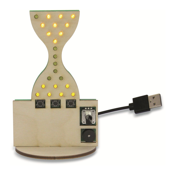
VARIOSAND
- The extraordinary
hourglass soldering kit
Item No.: 76700
Advertisement

Related Manuals for Sol-Expert VARIOSAND


Summary of Contents for Sol-Expert VARIOSAND
- Page 1 VARIOSAND - The extraordinary hourglass soldering kit Keep the address of the company. SOL-EXPERT SOL-EXPERT group group Not suitable for children under 3 group group years! - Contains small parts! Can be set from: 1 minute to 109 minutes Item No.: 76700...
-
Page 2: Important Notes
Important notes! For children and youngsters we recommend: Assembly and soldering should be supervised by an adult with soldering skills! SAFETY NOTES: This kit is only intended to be USB powered. Never connect the kit to 230 V mains voltage! This poses an absolute danger to life! Keep these instructions for future reference! They contain important information. - Page 3 "sand" has visually trickled down from the top to the bottom, the beeper sounds to tell you the egg is ready! With VARIOSAND you can also store 3 separate times that you can then simply retrieve at the touch of a button. It might look something like this: On button "1"...
- Page 4 VARIOSAND - The extraordinary hourglass Parts list Check the parts: Piezo (J5) Qty. Part Value / Designation Encoder (SW1) Encoder 76700 USB connecting cable 40 cm 3 mm LED (LED1-22) yellow Set of wooden parts 4 parts Resistor (R5-R16) 330 ohms...
- Page 5 ASSEMBLY INSTRUCTIONS Resistor colour code: Preparation Set out and sort all parts. This will make it easier for you to later identify 330 ohms 1.5K ohms 180 ohms the individual parts you will need during the steps. And it doesn't hurt to tidy up your work space so you can quickly find all parts.
- Page 6 Prepare resistors with the bending tool. In order for the small resistors R1-R16 and R19-R22 to fit properly between the soldering points, the Resistors conntecting wires must be bent exactly in the correct location. To make this easier, we have designed a to bend: simple yet functional bending tool.
- Page 7 Now the first resistors are soldered Shorten any protruding wires. You will now need these parts: onto the PCB After soldering, cut off the protruding Place the PCB in front of you so that you can 10K ohms read the resistor values printed in white. Then wires on the back, shorten to approx.
- Page 8 And again trim the protruding wires. You will now need these parts: After soldering, cut off the protruding 1.5K ohms 330 ohms R2+R4 wires on the back, shorten to approx. 12 x R5 - R16 2 mm with the side cutter. 4.7K ohms 180 ohms R1+R3...
- Page 9 Now solder on the two capacitors and ... and then trim the protruding wires. You will now need afterwards the quartz... the following parts: After soldering, cut off the protruding 22 pF/10V wires on the back, shorten to approx. C2+C3 2 mm with the side cutter.
- Page 10 Now we come to the heart of the circuit: the processor! To make it easier for the processor to slide between the soldering points, you can bend all the legs inwards a little. (Image 1) When plugging in the processor, you must pay attention to its alignment. The processor has a notch (rounding), which must be oriented to the left when you insert it.
- Page 11 Solder the capacitors C4 + Solder on the transistors and capacitor. Bend the middle leg of the transistors slightly C5 and then C1, trim solder backwards (image 1), pay attention to the alignment (image 2) and solder the transistors. wire to 2 mm. Pay attention to the polarity of capacitor C6, which is now soldered on.
- Page 12 Solder on the buttons. Now come the LEDs. The buttons are soldered onto the on Solder on one LED after the other. It is essential that you observe the polarity the back. Therefore, turn the PCB over of the LED. The longer leg is always PLUS "+" and has to be in the soldering and only then solder on the buttons.
- Page 13 PIEZO and encoder. Solder the USB connection cable. Ensure that the polarity of the piezo is correct. First thread both individual cables (red and pink/white) together approx. You will find a "+" symbol on both the circuit 1.5 cm through the two holes. To solder, push the strand of each cable through board and the piezo.
- Page 14 Glue the hourglass to the base plate. Mount the front cover. Apply a little wood glue to the areas Before attaching the wooden front, double- marked in red and then then press the check that all the protruding wires have been hourglass onto the the base plate.
- Page 15 Mount the cable strain relief. Fasten the cable tie tightly around the cable with approx. 1.5 cm distance to the cable casing (see image 1). Trim the protruding piece of the cable tie with the side cutters. Then apply wood glue to the first cable fixings (image 2), slide it over the cable and press it into the base.
-
Page 16: Visual Inspection
VISUAL INSPECTION: Now connect the USB cable of the VARIOSAND hourglass to a USB port (e.g. power bank or mobile phone power supply). Now all the LEDs should trickle down from the top like the sand in a real Just sit back and relax and let hourglass. - Page 17 If the button on the rotary encoder is now held down for approx. 2 seconds, the middle LED starts to flash briefly. Then the lower right LED lights up. If the rotary encoder is now turned clockwise, more and more LEDs will be switched on. In the lower section of VARIOSAND (highlighted in blue in the example below)
- Page 18 When all the "sand" has reached the lower area and the time has expired, the buzzer sounds. You can switch it off by pressing any button or switch. The memory buttons VARIOSAND can store a total of three freely selectable times, which can then be retrieved simply by pressing a button. And this is how it works: Programme the desired time:...
- Page 19 Briefly pressing the rotary encoder button interrupts the programme sequence and VARIOSAND automatically returns to the switch-on state. And when the eggs are boiled, the pizza is ready, the smell of cake is wafting through your home and you no longer need VARIOSAND, unplug it and keep it safe and dry for the next time.
- Page 20 Other great SOL-EXPERT group soldering kits: Click here for the instructions: Hier geht es zur Anleitung: Binary Clock soldering kit TrainYourBrain soldering kit Cliquez ici pour les instructions: Klik hier voor de instructies: Shows the time digitally! Keep your brain fit! Item no.: 76334...
Need help?
Do you have a question about the VARIOSAND and is the answer not in the manual?
Questions and answers