Advertisement
Quick Links
10+
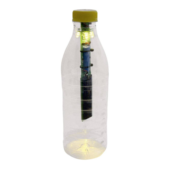
PET Bottle Solar Lamp
Soldering and DIY kit - pimp your PET bottle!
Contents:
You will also need:
Soldering iron, solder, tweezers,
pen, hot glue gun, side cutters
We recommend:
Assembly and soldering should be supervised
by an experienced person!
Return the device to a
certified provider at the
end of its useful life!
Item No. 79334
Important:
When buying the PET
bottle, ensure the neck is
at least 28 mm wide!
SOL-EXPERT
group
group
Advertisement

Related Manuals for Sol-Expert DoubleLight


Summary of Contents for Sol-Expert DoubleLight
- Page 1 Return the device to a certified provider at the SOL-EXPERT group group end of its useful life! PET Bottle Solar Lamp Soldering and DIY kit - pimp your PET bottle! Item No. 79334 Contents: Important: When buying the PET bottle, ensure the neck is...
- Page 2 ! SAFETY NOTES ! Read the full instructions before use and keep in a safe location for future reference. They contain important information. We assume no liability for personal injury or property damage due to improper handling or failure to observe the safety notes! This will void the warranty/guarantee.
- Page 3 Used batteries contain valuable raw materials which can be recycled. You can also return your used rechargeable battery to us: SOL-EXPERT group, Mehlisstrasse 19, 88225 Baindt, Germany. You can purchase new rechargeable batteries for this product directly from us.
- Page 4 How the solar-powered PET bottle lamp works With this cool soldering kit you can turn a standard PET bottle (min. neck width 28 mm) into a great solar lamp. The solar cell charges the rechargeable battery in this kit during the day. When it starts to get dark, the lamp automatically switches on and stays on all night - depending on the battery level.
- Page 5 Parts list: check, sort and tick Qty. Part Value / Designation 79332 Resistor (R8) 5.1 Ohm Resistor (R2) 20 Ohm Resistor (R1) 47 Ohm Resistor (R10) 1K Ohm Resistor (R7) 20K Ohm Resistor (R3/R4/R5/R6) 100K Ohm Diode (D1/D2) 1N5817 Diode (D3) 3V3 500 mA LED 5 mm (LED2 - LED5) soft white...
- Page 6 INSTRUCTIONS Laser cut wood bending tool To ensure the resistors and diodes fit in the middle between the eyelets, the connection wires on the parts must be bent at just the right position. To help we this we designed a simple yet functional bending tool. Simply place the parts in the respective opening (R = resistor / D1 / D2 = black diode / D3 = red diode), then bend the wires down straight along the...
-
Page 7: Required Parts
Bend the Diodes second leg down Soldering the PCB Important: Ensure the individual parts are always resting on the PCB before Diodes soldering them in place! Solder diode D3. Note the polarity (direction) - polarity shown on the PCB! Required parts Ensure the part is properly seated on the PCB before... -
Page 8: Required Parts
Trim excess wires. Once soldered in place, use side cutters to trim the excess wire at the back to approx. 2 mm. Solder 9 resistors in place, noting the ratings. The polarity is not important with the resistor. Trim excess wires after soldering Required parts 20 Ohm... - Page 9 Solder diode D1 and D2. Note the polarity (direction), polarity shown on the PCB! Ensure the Required parts part is properly D1/D2 1N5817 seated on the PCB before soldering in place! Note the polarity! The Solder socket J1 for the battery. socket has a notch.
-
Page 10: Table Of Contents
Solder potentimeter P1 and switches SW1/SW2/SW3. Trim excess legs. The polarity is not important. Required parts SW1/SW2/SW3 Ensure the part is properly seated on the PCB before soldering in place! Solder transistors T1 & T3. Note the polarity (1)! Bend the middle leg of the transistor slightly back (2). - Page 11 Rounded Rounded The black body of the side side transistor is approx. 2 - 3 mm from the PCB surface. Flat side Flat side Flat side Flat side Install and solder LED5 (yellow dot in the middle of the LED lens) 4 mm from the PCB. Note the polarity! The bending tool is also used as a spacer here.
- Page 12 Image A Insert long "+" leg here Insert short "-" leg here Result...
- Page 13 Install and solder LED2 (yellow dot in the middle of the LED lens) to the back of the PCB 4 mm from the PCB. Same as step H. Required parts LED2 LED must have a yellow dot in the middle viewed from above! Insert long Insert short...
- Page 14 Now solder LED3 and LED4 (both with yellow dot in the middle of the LED lens). LED3 goes in the front, LED4 is the last for the back. Required parts LED3 LED4 LED must have a yellow dot in the middle viewed from above! LED3...
- Page 15 Now solder LED1 (rainbow) to the PCB. Use the spacer again. LED1 is fitted from the front. Note the correct polarity. Long leg "+", short leg "-". This LED does not have a yellow dot in the middle. After soldering, bend LED1 downward. Required parts LED1...
- Page 16 Solder the cables to the solar cells. First presolder the contacts for the solar cell (i.e. apply some solder to both solder contacts), then solder the two tinned cable ends to the contacts. Attention: red cable to " " and black cable to "-", the loose cable ends pointing toward the middle of the solar cell.
- Page 17 Now comes the red cable. Use eyelet "Solar1+". When gluing the solar cell in place, ensure: 1. the solder contacs for the solar cell are visible in cut-out "1". 2. Cut-out "2" stays almost completely open. Solder contacts visible Cut-out "2" Cut-out „1"...
- Page 18 Insert the cables of the remaining solar cell through the bottom cut-out (yellow marking). Solder the red cable to eyelet Solar2+, the black cable to Solar2-. Raise the solar cell, apply hot glue to the PCB (yellow area) and lower the solar cell. Hold the solar cell down until the glue has cooled down.The solder points for the solar cell must again be inside the cut-out.
- Page 19 Now install the battery Connect the plug to the socket, slide the battery into the cut-out and secure with 2 cable ties. Then trim the ends of the cable ties with a side cutter. Exactly here: cable tie end TEST RUN: You have now soldered everything that was necessary and are now ready for the first test run.
- Page 20 Lamp comes on? EXCELLENT JOB If it doesn't come on, check the solder points and verify all parts are soldered the correct way around. (see Troubleshooting p. 24) Now glue the PCB into the bottle Important note: Glue must not run onto this red area. If it does, you will need to carefully pick out the glue or the bottle will not close.
- Page 21 Ensure the PCB is Now slide the finished PCB upright in the cap into the cap adapter. adapter.
- Page 22 Then from the other side. Now first carefully apply hot Don't forget: the "red glue between the PCB and zone" is off limits for glue. the cap adapter from one side. No glue in "red zone"! Apply glue here INSTRUCTIONS FOR USE: Set SW1 to either winter or summer mode.
- Page 23 INSTRUCTIONS FOR USE: Lamp on switch. Choose white or This switch will multi-colour LED? normally always be You can use the set to "ON". However, SW3 switch to switch following assembly or between white and after long periods of colour change. poor weather the battery may not be potentiometer...
- Page 24 TROUBLESHOOTING: No LEDs come on: Check all solder points for short-circuits. Specifically check the transistors, as the legs are close together and solder can easily come in between solder points. A single LED does not light up: Check the solder points of the LEDs. Did you install the LEDs the correct way around? Since the legs have already been trimmed, you can determine the polarity by the inside of the LED.
- Page 25 Other cool kits "TrainYourBrain" Soldering Kit The "TYB" PCB kit is a soldering kit ideal for anybody who likes to use a soldering iron or soldering station. TYB improves memory and concentration by memorising and repeating number sequences with different combinations and speeds.
- Page 26 WIRING DIAGRAM:...
- Page 28 Art.Nr.: 79334 SOL-EXPERT group, C.Repky Mehlisstrasse 19 - D-88255 Baindt Tel.: +49 (0)7502 - 94115-0, Fax: +49 (0)7502 - 94115-99 info@sol-expert-group.de, www.sol-expert-group.de Änderungen und Irrtümer vorbehalten 4 037373 793341 © September 2020, Christian Repky...
Need help?
Do you have a question about the DoubleLight and is the answer not in the manual?
Questions and answers