Advertisement
Quick Links
Instructions for
Instructions
for use
Mode d'emploi
Mode d'emploi
Bedienungsanleitung
Bedienungsanleitung
Instrucciones de uso
Instrucciones de uso
Manuale d'instruzioni
Manuale d'instruzioni
Bruksanvisning
Bruksanvisning
SKF TMEA 2
SKF TMEA 2
use
Gebruiksaanwijzing
Gebruiksaanwijzing
Instrucções de utilização
Instrucções de utilização
Brugervejledning
Brugervejledning
Käyttöohje
Käyttöohje
!"#$%&' ()*+#'
!"#$%&'
()*+#'
Advertisement

Related Manuals for SKF TMEA 2


Summary of Contents for SKF TMEA 2
- Page 1 SKF TMEA 2 SKF TMEA 2 Instructions Instructions for for use Gebruiksaanwijzing Gebruiksaanwijzing Mode d’emploi Mode d’emploi Instrucções de utilização Instrucções de utilização Bedienungsanleitung Bedienungsanleitung Brugervejledning Brugervejledning Instrucciones de uso Instrucciones de uso Käyttöohje Käyttöohje Manuale d’instruzioni Manuale d’instruzioni !"#$%&' !"#$%&' ()*+#'...
- Page 2 E E U U - - D D E E C C L L A A R R A A T T I I O O N N O O F F C C O O N N F F O O R R M M I I T T Y Y S S A A F F E E T T Y Y R R E E C C O O M M M M E E N N D D A A T T I I O O N N S S 1 1 .
- Page 3 E E U U - - D D E E C C L L A A R R A A T T I I O O N N O O F F C C O O N N F F O O R R M M I I T T Y Y S S A A F F E E T T Y Y R R E E C C O O M M M M E E N N D D A A T T I I O O N N S S 1 1 .
-
Page 4: Eu Declaration Of Conformity
EU-DECLARATION OF CONFORMITY EU-DECLARATION OF CONFORMITY We, SKF Maintenance We, SKF Maintenance Products, Kelvinbaan 16, Products, Kelvinbaan 16, 3439 MT Nieuwegein, The N 3439 MT Nieuwegein, The Netherlands, declare that the etherlands, declare that the SHAFT ALIGNMENT TOOL... -
Page 5: Safety Recommendations
• The equipment should not be used in areas where there is a risk for explosion. • Do not expose the equipment to high humidity or direct contact with water. • All repair work should be taken care of by an SKF repair shop. Shaft alignment tool SKF TMEA 2... - Page 6 Principle of operation The TMEA 2 system uses two measuring units both provided with a laser diode and a positioning detector. As the shafts are rotated through 180° any parallel misalignment or angular misalignment causes the two laser lines to deflect from their initial relative position.
- Page 7 Movable machine. The position with the measuring units in an upright position is defined as 12 o'clock while 90° left or right is defined as 9 and 3 o'clock. Fig. 4. The analogy of a clock A Stationary B Movable C Movable machine Shaft alignment tool SKF TMEA 2...
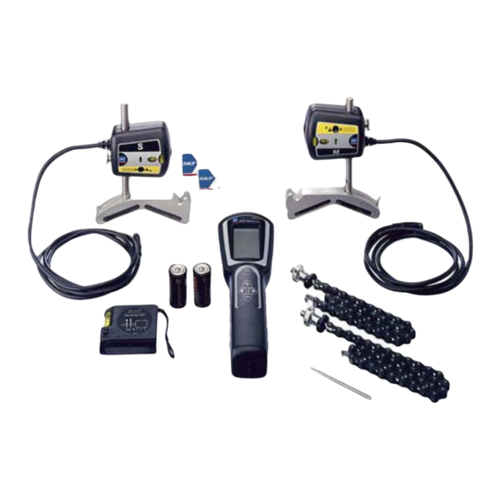
- Page 8 E g SHAFT ALIGNMENT TOOL l i s h The following components are included with the TMEA 2 tools: • Display unit • 2 measuring units with spirit levels • 2 magnetic / mechanical shaft fixtures • 2 locking chains •...
- Page 9 Front feet values M Indication of parallel coupling value direction N Indication of angular coupling value direction P Position (9/12/3 o'clock) of measuring units R Low battery S Imperial or metric units Fig. 6. Display unit Shaft alignment tool SKF TMEA 2...
- Page 10 E Chain fixation screw B Spirit level F Locking chain C Wheel for vertical fine G Magnetic / mechanical fixture adjustment of laser line H Connection rod D Warning LED Release / tightening knob SKF TMEA 2 Shaft alignment tool...
- Page 11 Operating humidity < 90% Carrying case dimensions 390 x 340 x 95 (15.4 x 13.4 x 3.7 in) Total weight (incl. case) 3.7 kg (8.1 lb) Calibration certificate valid for two years Warranty 12 months Shaft alignment tool SKF TMEA 2...
- Page 12 Feet on the ground If there is any doubt whether the machine is resting equally on all feet please check for so called "soft foot". The procedure for this operation is described in chapter 3.10. SKF TMEA 2 Shaft alignment tool...
- Page 13 If it is not possible to attach the fixtures directly to the shafts (e.g. in case of space problems) the fixtures can be attached to the coupling. Note! It is highly recommended to position the measuring units at equal distance from the middle of the coupling. Shaft alignment tool SKF TMEA 2...
- Page 14 Switch on the display unit by pressing the ON/OFF button. You will now be prompted to enter the machine dimensions as per chapter 3.5. If no button is pressed within 60 minutes, the unit will turn off automatically. SKF TMEA 2 Shaft alignment tool...
- Page 15 B: The distance between the M-marked measuring unit and the front pair of feet of the Movable machine. C: The distance between the front feet and the rear feet of the Movable machine. Fig. 10. Machine dimensions Shaft alignment tool SKF TMEA 2...
- Page 16 Confirm the setting of each value by pressing the "next" button. Note! If you need to go back and change values already entered use the "previous" button. Fig. 11. Distances A, B and C SKF TMEA 2 Shaft alignment tool...
- Page 17 Aiming the laser lines a) Put the two measuring units in the 12 o'clock position with the help of the spirit levels (fig. 12). Fig. 12. The 12 o clock position Shaft alignment tool SKF TMEA 2...
- Page 18 Aim the laser lines so that they hit in the centre of the target of the g l i s h opposite measuring unit (fig. 13). Fig. 13. Hit the target A Laser line SKF TMEA 2 Shaft alignment tool...
- Page 19 For the fine adjustment in height use the adjustment wheels on the measuring units. Fig. 14. Adjustment mechanism A Vertical positioning of measuring unit B Horizontal rotation of measuring unit C Vertical fine adjustment of laser Shaft alignment tool SKF TMEA 2...
- Page 20 Fig. 15. Rough alignment A The beam moves outside the detector area B Adjust the beam to half the travel C Direct the machine to hit the centre SKF TMEA 2 Shaft alignment tool...
- Page 21 (fig. 16). As described earlier (chapter 1.3) we use the analogy of a clock to describe the different positions. Fig. 16. Display guides you to the 9 o'clock position Shaft alignment tool SKF TMEA 2...
- Page 22 By pressing the "previous" Fig. 18. Rotate to the 3 o'clock button, you will reverse the position process in order to repeat any of the measurement steps or to adjust any of the machine dimensions. SKF TMEA 2 Shaft alignment tool...
- Page 23 The F1 value indicates the relative position of the front pair of feet of the Movable machine. The F2 value indicates the relative position of the rear pair of feet of the Movable machine. Shaft alignment tool SKF TMEA 2...
- Page 24 Table 1. Acceptable maximum misalignment mm/100 mm 0.001”/1” 0.001” 0 - 1000 0.10 0.13 1000 - 2000 0.08 0.10 2000 - 3000 0.07 0.07 3000 - 4000 0.06 0.05 4000 - 6000 0.05 0.03 SKF TMEA 2 Shaft alignment tool...
- Page 25 Fig. 22. Vertical alignment machine. Observe the coupling and feet values live adjustment. After having carried out the vertical alignment proceed to the horizontal alignment (chapter 3.8.3). Shaft alignment tool SKF TMEA 2...
- Page 26 If the measured coupling values are within the tolerances, no sideways adjustment is necessary. b) If the measured coupling values are higher than the acceptable tolerances check the recommended correction on the feet. Fig. 24. Horizontal alignment SKF TMEA 2 Shaft alignment tool...
- Page 27 To verify the alignment of the machinery, it is recommended to execute the measuring procedure once again. To do so, go back by using the previous button until you reach the first measuring step (9 o'clock position) and continue as per chapter 3.7. Shaft alignment tool SKF TMEA 2...
- Page 28 E g l i s h This page has been intentionally left blank. SKF TMEA 2 Shaft alignment tool...
- Page 29 28. 4. Position the measuring units in the 12 o'clock position. 5. Press Next to zero the display values. Fig. 28. Soft foot display Shaft alignment tool SKF TMEA 2...
- Page 30 8. Repeat steps 5 to 8 for the remaining feet. The soft foot is now checked and corrected. 9. Press + and - simultaniously to leave the soft foot mode and enter the measuring sequence. SKF TMEA 2 Shaft alignment tool...
- Page 31 ALIGNMENT REPORT In order to facilitate recording of the alignment operation, the TMEA 2 is provided with a set of alignment reports. The report contains the following data fields: a) Name of the equipment b) Name of the operator c) Date...
- Page 32 E g l i s h SKF TMEA 2 Shaft alignment tool...
-
Page 33: Advanced Use
Make sure that the display unit is switched ON. b) Check the cables and connectors. Assure that all cables are properly connected. c) Check to see if the measuring units' warning LEDs flash. d) Replace the batteries. Shaft alignment tool SKF TMEA 2... - Page 34 Check if there is a soft foot condition. b) Check if there are any loose mechanical parts, play in bearing or movements in the machinery. c) Check the status of foundation, base plate, bolts and existing shims. SKF TMEA 2 Shaft alignment tool...
-
Page 35: Maintenance
Flat batteries will be indicated by the battery signal on the display. Replacement of measuring units or display unit Both measuring units are calibrated in pairs and hence they must be replaced as a pair. Shaft alignment tool SKF TMEA 2...
Need help?
Do you have a question about the TMEA 2 and is the answer not in the manual?
Questions and answers