
Subscribe to Our Youtube Channel
Related Manuals for ADLINK Technology DEX-100

Summary of Contents for ADLINK Technology DEX-100
- Page 1 DEX-100 Data Extraction System User’s Manual Manual Rev.: Dec. 30, 2017 Revision Date: 50-100 Part No: Leading EDGE COMPUTING...
- Page 2 Leading EDGE COMPUTING Revision History Revision Release Date Description of Change(s) Dec. 30, 2017 Initial Release...
-
Page 3: Preface
DEX-100 Preface Copyright 2017 ADLINK Technology, Inc. This document contains proprietary information protected by copy- right. All rights are reserved. No part of this manual may be repro- duced by any mechanical, electronic, or other means in any form without prior written permission of the manufacturer. - Page 4 Leading EDGE COMPUTING Conventions Take note of the following conventions used throughout this manual to make sure that users perform certain tasks and instructions properly. Additional information, aids, and tips that help users perform tasks. NOTE: NOTE: Information to prevent minor physical injury, component dam- age, data loss, and/or program corruption when trying to com- plete a task.
-
Page 5: Table Of Contents
DEX-100 Table of Contents Revision History..............ii Preface ..................iii List of Tables................ix List of Figures ................ xi 1 Introduction ................ 1 Features................2 Specifications............... 3 Mechanical Drawings............5 Front Panel I/O Connectors ..........8 1.4.1 Power Button .............. 9 1.4.2... - Page 6 Leading EDGE COMPUTING Unpacking Checklist ............23 Adaptors & Additional Accessories ........23 Wall Mounting ..............23 DIN Rail Mounting.............. 26 2.4.1 DIN Rail Mount w/ Right Side Up......26 2.4.2 DIN Rail Mount w/ Left Side Up ........ 28 Driver Installation ...............
- Page 7 DEX-100 Getting Service..............69 Table of Contents...
- Page 8 Leading EDGE COMPUTING viii Table of Contents...
-
Page 9: List Of Tables
DEX-100 List of Tables Table 1-1: Power Button LED Indicator Legend ......9 Table 1-2: VGA Out Pin Assignment ......... 10 Table 1-3: DisplayPort Pin Assignment ........11 Table 1-4: PS/2 Port Pin Assignment ........11 Table 1-5: COM1 and COM2 Connectors Pin Assignments..12 Table 1-6: USB 2.0 Pin Assignments ........ - Page 10 Leading EDGE COMPUTING This page intentionally left blank. List of Tables...
-
Page 11: List Of Figures
DEX-100 List of Figures Figure 1-1: Front View................ 5 Figure 1-2: Top View................6 Figure 1-3: (Right) Side View ............. 6 Figure 1-4: (Left) Side View ............... 7 Figure 1-5: Rear Side View ..............7 Figure 1-6: Front Panel I/O ..............8 Figure 1-7: VGA Out Connector............ - Page 12 Leading EDGE COMPUTING This page intentionally left blank. List of Figures...
-
Page 13: Introduction
The DEX-100 utilizes the DDS (Data Distribution Services) proto- col to deliver full data availability in real time, enhancing reliability and efficiency. Remote control is also available. -
Page 14: Features
Pre-installed Software DEX-PRO in DEX-100 for KB/MS script edits and image data transformation. Leading EDGE COMPUTING 1.1 Features Non-intrusive system VGA/DVI output Port support Remote monitoring by PS/2 and USB keyboard mouse devices Real-time data extraction and OP screen presentation ... -
Page 15: Specifications
DEX-100 1.2 Specifications System Processor Quad core Intel® Atom® processor E3950 Operating System Windows 10 IoT Enterprise 64 DDR3L 1066 4GB Storage 128 GB SSD I/O Interface 2x GbE LAN (Intel® I210-IT) 2x COM (2x RS-232/422/485) 2x USB 2.0 + 2x USB 3.0 + 2x USB Micro-B ... - Page 16 Leading EDGE COMPUTING Communication DDS (Distributed Data Service), REST Protocol and Interface Field Bus Modbus TCP and Modbus RTU Communication Environmental & Electrical Operating Standard: 0 to 50°C Temperature Storage Temperature -40°C to 85°C Humidity Approx. 95% @40°C (non-condensing) Operating 5 Grms, 5-500Hz, 3 axes w/ SD/ Vibration mSATA SSD mSATA SSD...
-
Page 17: Mechanical Drawings
DEX-100 1.3 Mechanical Drawings All dimensions shown are in millimeters (mm) unless otherwise stated. NOTE: NOTE: Figure 1-1: Front View Introduction... -
Page 18: Figure 1-2: Top View
Leading EDGE COMPUTING Figure 1-2: Top View Figure 1-3: (Right) Side View Introduction... -
Page 19: Figure 1-4: (Left) Side View
DEX-100 Figure 1-4: (Left) Side View Figure 1-5: Rear Side View Introduction... -
Page 20: Front Panel I/O Connectors
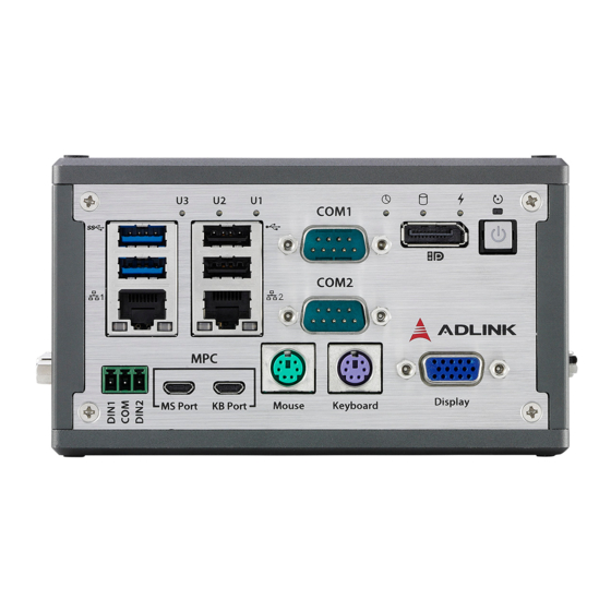
Leading EDGE COMPUTING 1.4 Front Panel I/O Connectors Figure 1-6: Front Panel I/O I/O connectors and controls on the DEX-100 front panel, as labeled, are as follows Power button VGA Out DisplayPort PS/2 keyboard port PS/2 mouse port ... -
Page 21: Power Button
DEX-100 1.4.1 Power Button System is turned on when button is pressed, and the power LED lit. If the system hangs, depressing the button for 5 seconds pow- ers down the unit. LED indicator functions as follows Power Button System Status... -
Page 22: Displayport
Leading EDGE COMPUTING Signal Signal ID2/RES ID1/SDA HSync RED_RTN VSync GREEN_RTN ID3/SCL BLUE_RTN Table 1-2: VGA Out Pin Assignment 1.4.3 DisplayPort The DisplayPort v1.1 connection supports up to 3840x2160 @ 30Hz. Figure 1-8: DisplayPort Connector Signal Signal CN_DP0_P CN_DP0_N CN_DP1_P CN_DP1_N CN_DP2_P CN_DP2_N... -
Page 23: Ps/2 Ports
DEX-100 Signal Signal CN_AUX_N DDP_HPD P3V3 Table 1-3: DisplayPort Pin Assignment 1.4.4 PS/2 Ports Two PS/2 ports support keyboard and mouse connection. Figure 1-9: PS/2 Port Pin Signal Description +DATA Data N/C [b] Ground +5 V DC at 275 mA... -
Page 24: Serial Ports (Com1 And Com2)
Leading EDGE COMPUTING 1.4.5 Serial ports (COM1 and COM2) COM1 supports RS-232/422/485 based on switch setting on the mainboard, with RS-232 the default, and COM2 supports RS-232 only. Figure 1-10: COM1 and COM2 Connectors Signal RS232 RS422 RS485 DCD# TXD422- 485DATA- TXD422+ 485DATA+... -
Page 25: Usb Ports
DEX-100 1.4.6 USB Ports 2 USB 3.0 and 2USB 2.0 ports each provide 5V power for con- nected devices. Figure 1-11: USB 2.0 Pin Signal UV0- UV0+ Table 1-6: USB 2.0 Pin Assignments Figure 1-12: USB 3.0 Signal USB3.0_P5VA USB2_CMAN... -
Page 26: Lan Ports
Leading EDGE COMPUTING Signal USB3A_CMRXN USB3A_CMRXP USB3A_CMTXN USB3A_CMTXP Table 1-7: USB 3.0 Pin Assignments 1.4.7 LAN Ports Two Gigabit Ethernet ports support the intel i210IT GbE controller, providing IEEE 802.3az Energy Efficient Ethernet IEEE 1588/802.1AS precision time synchronization IEEE 802.3Qav traffic shaper ... -
Page 27: Table 1-8: Lan Port Pin Definitions
DEX-100 LED1 LED2 Figure 1-13: LAN Port 10BASE-T/100BASE-TX 1000BASE-T LAN_MDI0+ LAN_MDI0- LAN_MDI1+ LAN_MDI2+ LAN_MDI2- LAN_MDI1- LAN_MDI3+ LAN_MDI3- Table 1-8: LAN Port Pin Definitions Activity No Link LED1 Orange Link Active (Active/Link) Blinking Data Activity 10 Mb connection LED2 Green 100 Mb connection... -
Page 28: Usb Micro-B Connector
Leading EDGE COMPUTING 1.4.8 USB Micro-b Connector USB keyboard and mouse bypass are provided by dual USB micro-b connectors, for connection to machine PC. Figure 1-14: USB Micro-b Connector Signal Description VBUS +5 V D− Data− Data+ Signal ground Table 1-10: USB Micro-b Connector Pin Definitions 1.4.9 DI Connectors Dual channel digital input function is provided within a terminal... -
Page 29: Led Indicators
DEX-100 Figure 1-15: DI Connector VCOM=0V VCOM=24V 24V: Enabled 0V: Enabled Digital input 2 0V/open: Disabled 24V/open: Disabled VCOM 24V: Enabled 0V: Enabled Digital input 1 0V/open: Disabled 24V/open: Disabled Table 1-11: DI Connector Pin Assignment 1.4.10 LED Indicators In addition to the LED of the power button, LEDs on the front panel indicate operations as follows. -
Page 30: Right Side I/O Connectors
Leading EDGE COMPUTING 1.5 Right Side I/O Connectors Figure 1-16: Right Side Panel I/O I/O connectors and controls on the DEX-100 right side panel, as labeled, are as follows VGA In PS/2 mouse port PS/2 keyboard port ... -
Page 31: Left Side I/O Connectors
DEX-100 1.6 Left Side I/O Connectors Figure 1-17: Left Side Panel I/O I/O connectors and controls on the DEX-100 left side panel, as labeled, are as follows DC Power Connector DVI port MPC DVI port 1.6.1 DC Power Connector Consists of V+, chassis ground, and V- pins. -
Page 32: Dvi Port
Leading EDGE COMPUTING Figure 1-18: Power Supply Connector Signal V+(DC_IN) GND(CHGND) V- (DGND) Table 1-13: DC Power Supply Pin Assignments 1.6.2 DVI Port Both DVI-D connectors, one for input and the other for output, sup- port 1920x1080 60Hz timing signal. Figure 1-19: DVI Port Signal V+(DC_IN) -
Page 33: Di/O Sample Circuits
DEX-100 Signal GND(CHGND) V- (DGND) Table 1-14: DVI Port Pin Assignments 1.7 DI/O Sample Circuits 1.7.1 Isolated Digital Input Circuits The input can accept voltages up to 24V, with extra 10kΩ input resistors (Rs). Connections between outside signals are as fol- lows. - Page 34 Leading EDGE COMPUTING This page intentionally left blank. Introduction...
-
Page 35: Getting Started
2.2 Adaptors & Additional Accessories Device adaptors and other optional accessories should only be obtained through your ADLINK dealer. For more information, see “Getting Service” on page 69. 2.3 Wall Mounting The DEX-100 provides 3 wall-mount configurations. Getting Started... -
Page 36: Figure 2-1: Wall-Mount With Rear Panel Up
Leading EDGE COMPUTING Figure 2-1: Wall-mount with Rear Panel Up Figure 2-2: Wall-mount with Right Side Panel Up Getting Started... -
Page 37: Figure 2-3: Wall-Mount With Left Panel Up
DEX-100 Figure 2-3: Wall-mount with Left Panel Up Attach the provided wall-mount brackets in the four screw holes on the underside of the chassis according to the desired configuration (wall-mount with rear panel up is shown as an example). Figure 2-4: Wall-mount Bracket Attachment (Rear panel up) -
Page 38: Din Rail Mounting
Leading EDGE COMPUTING 2.4 DIN Rail Mounting DEX-100 DIN rail installation is provided in right side up and left side up configurations. 2.4.1 DIN Rail Mount w/ Right Side Up 1. Place the terminal plate with VGA label up and secure the provided DIN rail bracket via the two screw holes on the rear side of the terminal plate. - Page 39 DEX-100 Getting Started...
-
Page 40: Din Rail Mount W/ Left Side Up
Leading EDGE COMPUTING 2.4.2 DIN Rail Mount w/ Left Side Up 1. Place the terminal plate with DVI label up and secure the provided DIN rail bracket via the two screw holes on the rear side of the terminal plate. 2. -
Page 41: Driver Installation
DEX-100 2.5 Driver Installation Due to lack of controller support under Windows 10, successful OS installation may be prevented. For available solutions, please contact your ADLINK representative. NOTE: NOTE: Download requisite drivers, as follows, for your system from http:// www.adlinktech.com and install. - Page 42 Leading EDGE COMPUTING This page intentionally left blank. Getting Started...
-
Page 43: A Appendix: Bios Setup
DEX-100. The BIOS setup program includes menus for configuring settings and enabling features of the DEX-100 series. Most users do not need to use the BIOS setup program, as the DEX-100 ships with default settings that work well for most configurations. -
Page 44: Main
Leading EDGE COMPUTING A.1 Main A.1.1 BIOS Information Shows current system BIOS core version, BIOS version and Board version. A.1.2 System Time/System Date Changes system time and date. Highlight System Time or System Date using the up or down <Arrow> keys. Enter new values using the keyboard then <Enter>. -
Page 45: Board Information
DEX-100 The time is in 24-hour format, for example, 5:30 A.M. appears as 05:30:00, and 5:30 P.M. as 17:30:00. NOTE: NOTE: A.1.3 Board Information Displays serial number, manufacturing date, last repair date, and MAC ID. As well, Runtime Statistics are listed, including total run- time, current runtime, power cycles, boot cycles, and boot reason. -
Page 46: Advanced
Leading EDGE COMPUTING A.2 Advanced Setting incorrect or conflicting values in Advanced BIOS Setup may cause system malfunction. CAUTION: BIOS Setup... -
Page 47: Cpu Configuration
DEX-100 A.2.1 CPU Configuration Active Processor Cores Number of cores to enable in each processor package. Intel Virtualization Technology When enabled, allows a VMM to utilize the additional hardware capabilities provided by Vanderpool Technology VT-d Enables/disables CPU VT-d Turbo Mode Enables/disables Turbo Mode. -
Page 48: Graphics Configuration
Leading EDGE COMPUTING Critical Trip Point Temperature threshold of the Critical Trip Point. Passive Cooling Trip Point Temperature threshold of the Passive Cooling Trip Point. A.2.2 Graphics Configuration GTT Size Sets GTT size Aperture Size Sets aperture size BIOS Setup... -
Page 49: Onboard Device Configuration
DEX-100 DVMT Pre-Allocated Sets size of DVMT 5.0 pre-allocated (fixed) graphics memory used by internal graphics device DVMT Total Gfx Mem Sets size of DVMT5.0 total graphic memory used by internal graphics device A.2.3 Onboard Device Configuration COM1 Control Selects COM1 mode from among RS232, RS422, and RS485. - Page 50 Leading EDGE COMPUTING HSUART Enables/disables LPSS HSUART support. LAN #1 (Intel I210) Enables/disables LAN device #1. LAN #2 (Intel I210) Enables/disables LAN device #2. Realtek Audio Support Enables/disables Realtek audio device. Serial Console Redirection COM 1 BIOS Setup...
- Page 51 DEX-100 Console Redirection Enables/Disables COM 1 console redirection. Console Redirection Settings (COM 1) Terminal Type Emulation: ANSI: Extended ASCII char set. VT100: ASCII char set. VT100+: Extends VT100 to support color, function keys, etc. VT-UTF8: Uses UTF8 encoding to map Unicode chars onto 1 or more bytes.
- Page 52 Leading EDGE COMPUTING Bits per second Selects serial port transmission speed, which must be matched on the other side, where long or noisy lines may require lower speeds. Data Bits Number of data bits Parity Parity bit can be sent with data bits to detect transmission errors, where Even: parity bit is 0 if the number of 1's in the data bits is even Odd: parity bit is 0 if number of 1's in the data bits is odd.
- Page 53 DEX-100 Recorder Mode When enabled, only text will be sent, to capture terminal data. Resolution 100x31 Enables/disables extended terminal resolution Legacy OS Redirection Resolution In legacy OS, the number of rows and columns supporting redi- rection Putty KeyPad Selects FunctionKey and KeyPad on PuTTY...
- Page 54 Leading EDGE COMPUTING COM 2 Console Redirection Enables/Disables COM 2 console redirection. Console Redirection Settings (COM 2) Terminal Type Emulation: ANSI: Extended ASCII char set. VT100: ASCII char set. VT100+: Extends VT100 to support color, function keys, etc. VT-UTF8: Uses UTF8 encoding to map Unicode chars onto 1 or more bytes.
- Page 55 DEX-100 Bits per second Selects serial port transmission speed, which must be matched on the other side, where long or noisy lines may require lower speeds. Data Bits Number of data bits Parity Parity bit can be sent with data bits to detect transmission...
- Page 56 Leading EDGE COMPUTING Recorder Mode When enabled, only text will be sent, to capture terminal data. Resolution 100x31 Enables/disables extended terminal resolution Legacy OS Redirection Resolution In legacy OS, the number of rows and columns supporting redi- rection Putty KeyPad Selects FunctionKey and KeyPad on PuTTY Redirection After BIOS Post When Bootloader is selected, Legacy Console Redirection is...
-
Page 57: Advanced Power Management
DEX-100 A.2.4 Advanced Power Management Power Supply Unit ATX: OS will turn off system power when shutdown, where AT mode does not support S3 & S4. State After G3 Specifies state to enter when power is re-applied after a power failure (G3 state). -
Page 58: Usb Configuration
Leading EDGE COMPUTING LAN #1 Wake Enables/disables onboard Wake on LAN for #1 LAN #2 Wake Enables/disables onboard Wake on LAN for #2 A.2.5 USB Configuration XHCI Hand-off A workaround for OS without XHCI handoff support, where XHCI ownership change should be claimed by the XHCI driver. USB Mass Storage Driver Support Enables/disables USB mass storage driver support. -
Page 59: Sata Configuration
DEX-100 USB transfer time-out Timeout value for Control, Bulk, and Interrupt transfers. Device reset time-out USB mass storage device Start Unit command timeout. Device power-up delay Maximum time the device will take before reporting to the Host Controller, where Auto uses default value, for a Root port 100 ms, and for a Hub port the delay is taken from the Hub descriptor. -
Page 60: Tpm Configuration
Leading EDGE COMPUTING A.2.7 TPM Configuration Security Device Support Enables/disables BIOS support for security device, when enabled, OS will not show the security device, and TCG EFI protocol and INT1A interface will not be available. BIOS Setup... -
Page 61: Network Stack Configuration
DEX-100 A.2.8 Network Stack Configuration Network Stack Enables/disables UEFI network stack BIOS Setup... -
Page 62: System Management
Leading EDGE COMPUTING A.2.9 System Management Shows SEMA firmware and bootloader versions and build dates. BIOS Setup... - Page 63 DEX-100 SEMA Features Shows features supported by the SEMA version. BIOS Setup...
- Page 64 Leading EDGE COMPUTING Temperatures Shows current CPU temperature, and current, startup, mini- mum, and maximum board temperatures. BIOS Setup...
- Page 65 DEX-100 Power Consumption Shows current input current and power, as well as system volt- ages. BIOS Setup...
- Page 66 Leading EDGE COMPUTING Flags Shows BMC flags with exception codes. BIOS Setup...
- Page 67 DEX-100 Power Up Lists Power-Up Watchdog status. BIOS Setup...
-
Page 68: Miscellaneous
Leading EDGE COMPUTING A.2.10 Miscellaneous OS Selection Allows selection of active OS. BIOS Setup... -
Page 69: Intel® I210 Gigabit Network Connection
DEX-100 A.2.11 Intel® I210 Gigabit Network Connection Blink LEDs Identifies the physical network port by flashing the associated LED. BIOS Setup... -
Page 70: Nic Configuration
Leading EDGE COMPUTING A.2.12 NIC Configuration Link Speed Specifies the port speed used for the selected boot protocol. Wake On LAN Enables server power-up using an in-band magic packet. BIOS Setup... -
Page 71: Security
DEX-100 A.3 Security If only the Administrator’s password is set, only access to Setup is limited and authorization requested only when enter- ing Setup. If only the User’s password is set, a password must NOTE: NOTE: be entered to boot or enter setup. In Setup the user has Admin- istrator rights. -
Page 72: Secure Boot
Leading EDGE COMPUTING A.3.1 Secure Boot Shows System Mode and Secure Boot status. Secure Boot is activated when Platform Key (PK) is enrolled, where System Mode is User/Deployed, and CSM function is disabled. NOTE: NOTE: BIOS Setup... -
Page 73: Boot
DEX-100 A.4 Boot Setup Prompt Timeout Number of seconds to wait for setup activation key, with 65535(0xFFFF) indicating infinite wait. Bootup NumLock State Sets keyboard NumLock status Quiet Boot Enables/disables Quiet Boot option Fast Boot Enables/disables boot with the minimal device initialization required to launch active boot option, with no effect on BBS boot options. -
Page 74: Save & Exit
Leading EDGE COMPUTING Sets number of seconds to wait for setup activation key. Boot Option Priorities Specifies the priority of boot devices, with all installed boot devices detected during POST and displayed, where selecting Boot Option # specifies the desired boot device. A.5 Save &... - Page 75 DEX-100 Save Changes and Reset Resets the system after saving changes. Discard Changes and Reset Resets system setup without saving any changes. Save Changes Saves changes to any setup options. Discard Changes Discards changes to any of the setup options.
- Page 76 Leading EDGE COMPUTING This page intentionally left blank. BIOS Setup...
-
Page 77: Important Safety Instructions
DEX-100 Important Safety Instructions For user safety, please read and follow all instructions, Warnings, Cautions, and Notes marked in this manual and on the associated device before handling/operating the device, to avoid injury or damage. S'il vous plaît prêter attention stricte à tous les avertissements et mises en garde figurant sur l'appareil , pour éviter des blessures... - Page 78 Leading EDGE COMPUTING Never attempt to repair the device, which should only be serviced by qualified technical personnel using suitable tools A Lithium-type battery may be provided for uninterrupted backup or emergency power. Risk of explosion if battery is replaced with one of an incorrect type;...
- Page 79 DEX-100 BURN HAZARD Touching this surface could result in bodily injury. To reduce risk, allow the surface to cool before touching. RISQUE DE BRÛLURES Ne touchez pas cette surface, cela pourrait entraîner des blessures. Pour éviter tout danger, laissez la surface refroidir avant de la toucher.
- Page 80 Leading EDGE COMPUTING This page intentionally left blank. Important Safety Instructions...
- Page 81 San Jose, CA 95138, USA Tel: +1-408-360-0200 Toll Free: +1-800-966-5200 (USA only) Fax: +1-408-360-0222 Email: info@adlinktech.com ADLINK Technology (China) Co., Ltd. 300 Fang Chun Rd., Zhangjiang Hi-Tech Park Pudong New Area, Shanghai, 201203 China Tel: +86-21-5132-8988 Fax: +86-21-5132-3588 Email: market@adlinktech.com...
Need help?
Do you have a question about the DEX-100 and is the answer not in the manual?
Questions and answers