Sign In
Upload
Manuals
Brands
ADLINK Technology Manuals
Data Loggers
DEX-100
ADLINK Technology DEX-100 Manuals
Manuals and User Guides for ADLINK Technology DEX-100. We have
1
ADLINK Technology DEX-100 manual available for free PDF download: User Manual
ADLINK Technology DEX-100 User Manual (81 pages)
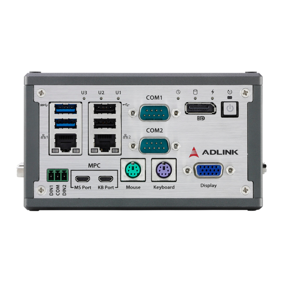
Data Extraction System
Brand:
ADLINK Technology
| Category:
Data Loggers
| Size: 4 MB
Table of Contents
Preface
3
Table of Contents
5
List of Tables
9
List of Figures
11
1 Introduction
13
Features
14
Specifications
15
Mechanical Drawings
17
Figure 1-1: Front View
17
Figure 1-2: Top View
18
Figure 1-3: (Right) Side View
18
Figure 1-4: (Left) Side View
19
Figure 1-5: Rear Side View
19
Front Panel I/O Connectors
20
Figure 1-6: Front Panel I/O
20
Figure 1-7: VGA out Connector
21
Power Button
21
Table 1-1: Power Button LED Indicator Legend
21
VGA out
21
Displayport
22
Figure 1-8: Displayport Connector
22
Table 1-2: VGA out Pin Assignment
22
Figure 1-9: PS/2 Port
23
PS/2 Ports
23
Table 1-3: Displayport Pin Assignment
23
Table 1-4: PS/2 Port Pin Assignment
23
Figure 1-10: COM1 and COM2 Connectors
24
Serial Ports (COM1 and COM2)
24
Table 1-5: COM1 and COM2 Connectors Pin Assignments
24
Figure 1-11: USB 2.0
25
Figure 1-12: USB 3.0
25
Table 1-6: USB 2.0 Pin Assignments
25
USB Ports
25
LAN Ports
26
Table 1-7: USB 3.0 Pin Assignments
26
Figure 1-13: LAN Port
27
Table 1-8: LAN Port Pin Definitions
27
Table 1-9: LAN Port LED Legend
27
DI Connectors
28
Figure 1-14: USB Micro-B Connector
28
Table 1-10: USB Micro-B Connector Pin Definitions
28
USB Micro-B Connector
28
Figure 1-15: DI Connector
29
LED Indicators
29
Table 1-11: DI Connector Pin Assignment
29
Table 1-12: LED Indicator Legend
29
Right Side I/O Connectors
30
Figure 1-16: Right Side Panel I/O
30
Left Side I/O Connectors
31
DC Power Connector
31
Figure 1-17: Left Side Panel I/O
31
DVI Port
32
Table 1-13: DC Power Supply Pin Assignments
32
Figure 1-18: Power Supply Connector
32
Figure 1-19: DVI Port
32
DI/O Sample Circuits
33
Isolated Digital Input Circuits
33
Table 1-14: DVI Port Pin Assignments
33
Figure 1-20: Digital Input Sample Application Circuit
33
2 Getting Started
35
Unpacking Checklist
35
Adaptors & Additional Accessories
35
Wall Mounting
35
Figure 2-1: Wall-Mount with Rear Panel up
36
Figure 2-2: Wall-Mount with Right Side Panel up
36
Figure 2-3: Wall-Mount with Left Panel up
37
Figure 2-4: Wall-Mount Bracket Attachment (Rear Panel Up)
37
DIN Rail Mounting
38
DIN Rail Mount W/ Right Side up
38
DIN Rail Mount W/ Left Side up
40
Driver Installation
41
A Appendix: BIOS Setup
43
Main
44
BIOS Information
44
System Time/System Date
44
Board Information
45
Advanced
46
CPU Configuration
47
Graphics Configuration
48
Onboard Device Configuration
49
Advanced Power Management
57
USB Configuration
58
SATA Configuration
59
TPM Configuration
60
Network Stack Configuration
61
System Management
62
Miscellaneous
68
Intel® I210 Gigabit Network Connection
69
NIC Configuration
70
Security
71
Secure Boot
72
Boot
73
Save & Exit
74
Important Safety Instructions
77
Advertisement
Advertisement
Related Products
ADLINK Technology DAQ-2010
ADLINK Technology DAQ-20 Series
ADLINK Technology DAQ-2005
ADLINK Technology DAQ-2006
ADLINK Technology NuDAQ DIN-96DI
ADLINK Technology DAQ-2206
ADLINK Technology DLAP3000-CFT1
ADLINK Technology DLAP-211-JNXS
ADLINK Technology DLAP-211-NanoS
ADLINK Technology DAQ/PXI-200 Series
ADLINK Technology Categories
Computer Hardware
Motherboard
PCI Card
Control Unit
Desktop
More ADLINK Technology Manuals
Login
Sign In
OR
Sign in with Facebook
Sign in with Google
Upload manual
Upload from disk
Upload from URL