
Related Manuals for Dametric BRM-DM1


Summary of Contents for Dametric BRM-DM1
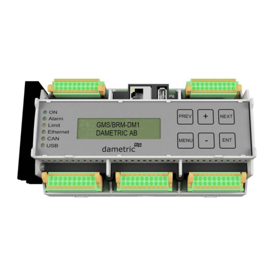
- Page 1 Dametric AB BRM-DM1/2 Installation manual dametric BRM-DM1 BRM-DM1 GMS Basic Refiner Module INSTALLATION MANUAL BRM-DM12 IM EN.docx October 14, 2019 Page 1 of 6...
- Page 2 Dametric AB BRM-DM1/2 Installation manual DOCUMENT REVISION ............................ 2 ARTICLE NUMBER SKC AND VALMET ........................ 2 USER MANUAL .............................. 2 TECHNICAL SPECIFICATION .......................... 2 INSTALLATION .............................. 3 .................................. 3 ENERAL .............................. 3 ONNECTOR PLACING ...
- Page 3 5 Installation 5.1 General This manual shows all connections to the module. Some of the functions are however not activated in the BRM-DM1 variant. All connections are done to 20-pole connectors with spring loaded sockets. Maximum allowed conduit area is 1.5mm or AWG 16.
- Page 4 Dametric AB BRM-DM1/2 Installation manual 5.4 Connector J2, AGS/CPM interface (option) +24VDCin Power supply input for AGS/CPM 0VDC Power ground +24VDCout Power supply output to AGS/CPM 0VDC Power ground 9,10 CAN2-H CAN2-interface H-signal (use twisted pair cable for CAN2-H and CAN2-L)
- Page 5 Dametric AB BRM-DM1/2 Installation manual 5.6 Connector J4, POM, VIM, TVD POM-T1 K-POT25/white (to POT-50 transducer) POM-T2 K-POT25/brown POM-T3 K-POT25/green POM-T4 K-POT25/yellow POM-T5 K-POT25/grey POM-T6 K-POT25/rose 0VDC K-POT25/shield 0VDC Signal ground VIM-EP K-VIMS25/white (to VIM-T2 transducer) VIM-SP K-VIMS25/brown VIM-SN K-VIMS25/green...
- Page 6 Dametric AB BRM-DM1/2 Installation manual 6 Contact dametric Sales, development, production and service: Dametric AB Jägerhorns Väg 19, 141 75 Kungens Kurva, Sweden Phone: +46-8 556 477 00 e-mail: service@dametric.se Web site: www.dametric.se BRM-DM12 IM EN.docx October 14, 2019 Page 6 of 6...
Need help?
Do you have a question about the BRM-DM1 and is the answer not in the manual?
Questions and answers