Table of Contents
Advertisement
Quick Links
Advertisement
Table of Contents

Related Manuals for Triton ARGO G60

Summary of Contents for Triton ARGO G60
- Page 1 ELLER ACHINE NSTALLATION ANUAL TDN 07103-00053 ORPORATE EADQUARTERS 21405 B S TREET , MS 39560 EACH PHONE: (800) 259-6672 FAX: (228) 868-9445 2014 Triton. All Rights Reserved. TRITON logo is a registered trademark of Triton © Systems of Delaware, LLC.
- Page 2 ARGO G60 I NSTALLATION ANUAL DOCUMENT UPDATES Date Description 01/30/14 Original ** WARNING ** Do NOT install the mechanism into the unit until the unit is bolted down to the ground. If the mechanism is installed prior to bolting the unit down, the unit could tip over and personal injury could occur.
-
Page 3: Table Of Contents
ANUAL NTRODUCTION The Triton ARGO G60 ATM is a lobby terminal designed for indoor use only. The following sections pro- vide the requirements for installing the ARGO G60 for your particular site location. To assist in preparing your site, a check list is provided of various steps that should be carried out prior to the arrival of the ATM. -
Page 4: Required Parts And Tools
ARGO G60 I NSTALLATION ANUAL EQUIRED ARTS AND OOLS TOOLS REQUIRED Torque wrench adjustable to at least 60 foot pounds, adjustable crescent wrench or ratchet wrench, hammer, 3/4” (19mm) socket, large fl at screwdriver, bubble level, 7/16” socket/box wrench, safety goggles, hearing protection, 1/4”... -
Page 5: Checklist
ARGO G60 I NSTALLATION ANUAL NVIRONMENTAL RECAUTION HECKLIST SITE PREPARATION CHECKLIST 1. Select site and design fl oor plan accordingly. 2. Ensure all environmental conditions are met. 3. Establish contractor and vendor schedules. 4. Check communication line requirements. 5. Plan installation and accessory needs before starting. -
Page 6: Dimensions
ARGO G60 I NSTALLATION ANUAL * IMPORTANT * AC power for the terminal should come from a dedicated source with an isolated ground. EDICATED ELEPHONE Dedicated source The ATM AC power feed will 3. Ensure the following telephone-line requirements be a dedicated line, to which no other electrical devices are met: are connected. -
Page 7: Cabinet Front View / Service
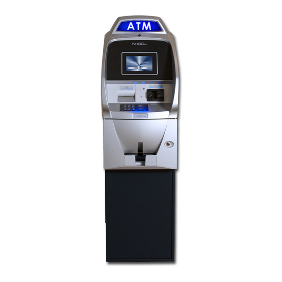
ARGO G60 I NSTALLATION ANUAL ABINET RONT Customer Access Dimensions Feature Height Top Function 46 15/16” [1193mm] #5 Key 36 1/2” (Main Keypad) [928mm] Card Reader 39 1/16” [992mm] 4 Receipt Printer 38 1/4” [972mm] Bill Tray 27 3/16” [690mm]... -
Page 8: Cabinet Side Views
ARGO G60 I NSTALLATION ANUAL ABINET IMENSIONS IEWS Right Left Right Left... -
Page 9: Cabinet Topper / Sign Area
ARGO G60 I NSTALLATION ANUAL BACKLIT GRAPHIC ABINET OPPER Front Side Rear ABINET... -
Page 10: Cabinet "Footprint
ARGO G60 I NSTALLATION ANUAL ABINET “F ” OOTPRINT... -
Page 11: Cabinet Decal Area
ARGO G60 I NSTALLATION ANUAL ABINET ECAL VISIBLE DECAL AREA SUGGESTED DECAL AREA... -
Page 12: Replacing Older Units
NSTALLATION ANUAL EPLACING LDER NITS When replacing older Triton ATMs with the ARGO G60, you may be able to use holes already drilled to install the ATM. See the table below for corresponding hole sites. ARGO G60 ABINET • 9100 with SDD (deep version) •... -
Page 13: Cabinet Installation
(P/N 06200-00066) anchor kit. The anchor kit is NOT supplied with the unit. Call Triton at 888-7-ATMGURUS for availability. * IMPORTANT * The ARGO G60 ATM is designed for INDOOR use only! **WARNING** DO NOT APPLY POWER TO THIS TERMINAL UNTIL THE INSTALLA-... -
Page 14: Unpack Atm
3 seconds to open the lock. the contents. Check the contents against the enclosed packing list and report To open the lock, turn the any missing parts to Triton. outer ring of the dial to the right (clockwise). After the 11. -
Page 15: Mark/Drill Mounting Holes
ARGO G60 I NSTALLATION ANUAL Mark/Drill Mounting Holes Mark the location of the cabinet mounting holes on the concrete fl oor. This is accomplished as described below: 1. Move the ATM to the location where it will be installed. Open the cabinet vault door at least 90° to improve access. Locate the four (4) anchor-bolt holes in the bottom of the cabinet (each corner). -
Page 16: Nstall Tandard Nchors
ARGO G60 I NSTALLATION ANUAL NSTALL TANDARD NCHORS LOOR OCKING ARGO ATM B OUNTING LAT WASHER NCHOR Anchor bolt installation illustration 1. Ensure the mounting location is free of all debris that might cause the cabinet to not be level. Use blower or vaccuum to remove any dust or particles. -
Page 17: Oute Ac Power And
ARGO G60 I NSTALLATION ANUAL Use anchor bolt in each mounting hole Hammer bolts snuggly into drilled holes 6. Ensure the cabinet is as level as possible given the fl oor conditions. Use a bubble level to verify this. If a bubble-level is not available, the cabinet can be “rocked”... - Page 18 Attach security bracket to lower left corner of cablinet as shown. The ARGO G60 unit has an additonal security feature with the additon of a special bracket between the upper and lower cabinets to secure cables and wiring running between the cabinets. This is already installed on the ARGO G60 from the factory.
- Page 19 ARGO G60 I NSTALLATION ANUAL POWER SUPPLY CORD SPECIFICATIONS For European applications, the power supply cord must conform to the following: 1. Two-conductor with Physical Earth (PE) ground. 2. IEC 320 molded connector on one end and molded plug on the other end.
- Page 20 PPENDIX OFTWARE ICENSE GREEMENT OMPLIANCE MISSION TATEMENTS...
- Page 21 Triton or its suppliers. The software is licensed for use on this specific Triton ATM product and may not be used on any other product. Otherwise, the supporting documentation, if any, may be copied only as essential for backup or archive purposes in support of your use of the ATM.
- Page 22 SOFTWARE, AT TRITON’S SOLE DISCRETION. Any warranty pertaining to the ATM, its mechanical components exclusive of the ATM software, shall be governed and controlled by any warranty given to you by Triton in a separate document accompanying this ATM. The foregoing limitation of liability and exclusion of certain damages will apply regardless of the success or effectiveness of other remedies.
- Page 23 Operation is subject to the following two (2) Changes or modifications not expressly approved conditions: by Triton Systems could void the regulatory compliance approval and the warranty. Use of this 1) This device may not cause harmful interference. product in a manner other than those described in...
- Page 24 ppendix ATM i nsTAllATion for ccessiBiliTy...
- Page 25 B - ATM i ppendix nsTAllATion for ccessiBiliTy A Guide to the ADA Guidelines 305. Clear Floor or Ground Space 305.1 General. Clear floor or ground space shall comply with 305. 305.2 Floor or Ground Surfaces. Floor or ground surfaces of a clear floor or ground space shall comply with 302.
- Page 26 B - ATM i ppendix nsTAllATion for ccessiBiliTy 308. Reach Ranges 308.1 General. Reach ranges shall comply with 308. 308.2 Forward Reach. 308.2.1 Unobstructed. Where a forward reach is unobstructed, the high forward reach shall be 48 inches (1220 mm) maximum and the low forward reach shall be 15 inches (380 mm) minimum above the finish floor or ground.
- Page 27 This document supersedes all other information provided by Triton for ATM installation for accessibility. Information provided in this manual is based on federal guidelines (ADA Accessibility Guidelines for Buildings and Facilities – ADAAG) as amended through January 1998. You should verify it has not been amended. States may also have accessibility codes.
- Page 28 B - ATM i ppendix nsTAllATion for ccessiBiliTy (a) Reach Depth Not More Than 10 inches (255 mm). Where the reach depth to the operable parts of all controls as measured from the vertical plane perpendicular to the edge of the unobstructed clear floor space at the farthest protrusion of the automated teller machine or surround is not more than 10 inches (255 mm), the maximum height above the finished floor or grade shall be 54 inches (1370 mm).
- Page 29 B - ATM i ppendix nsTAllATion for ccessiBiliTy 4.2.4 Clear Floor or Ground Space for Wheelchairs. 4.2.4.1 Size and Approach. The minimum clear floor or ground space required to accommodate a single, stationary wheelchair and occupant is 30 inches by 48 inches (760 mm by 1220 mm) (see Fig.4a). The minimum clear floor or ground space for wheelchairs may be positioned for forward or parallel approach to an object (see Fig.
- Page 30 B - ATM i ppendix nsTAllATion for ccessiBiliTy Figures 4d. Clear Floor Space in Alcoves. Figures 4e. Clear Floor Space in Alcove. For a side approach, where the depth of the alcove is equal to For a side approach, where the depth of the alcove is greater or less than 15 inches (380 mm), the required clear floor space than 15 inches (380 mm), then in addition to the 48-inch (1220 is 30 inches by 48 inches (760 mm by 1220 mm).
- Page 31 B - ATM i ppendix nsTAllATion for ccessiBiliTy 4.2.6 Side Reach. If the clear floor space allows parallel approach by a person in a wheelchair, the maximum high side reach allowed shall be 54 inches (1370 mm) and the low side reach shall be no less than 9 inches (230 mm) above the floor (Fig. 6(a) and 6(b)).
Need help?
Do you have a question about the ARGO G60 and is the answer not in the manual?
Questions and answers