Table of Contents
Advertisement
Quick Links
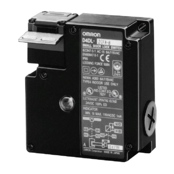
D4DL
Locking Safety-Door Switch
Compact, Locking Safety Door Switch
with Dual Key Entry
Two types in the series: Mechanical-lock
H
models that lock automatically when the
Operation Key is inserted, and
solenoid-lock models that lock when voltage
is applied to the solenoid
Rotatable operating head provides four
H
possible key entry slots
Incorporates an indicator that shows
H
operation status at a glance
Double-insulation structure (with
H
requires no grounding terminals
The switch contact is opened by a positive
H
opening mechanism (NC contacts only) The
EN-approved positive opening mechanism
is indicated by
on the switch
Standards and EC Directives:
H
•
Conforms to the following EC Directives:
Machinery Directive
Low Voltage Directive
EN50047
EN1088
SUVA
Approved Standards
Agency
Standard
TÜV Rheinland
EN60947-5-1
BIA
GS-ET-19
UL (see note)
UL508, CSA C22.2
No.14
SUVA
SUVA
Note: CSA C22.2 No. 14 compliance was verified and approved
by UL (Marked with
mark)
File No.
J9650735
(Positive opening:
approved)
Mechanical lock: 9610568
Solenoid lock: 9704054
E76675
Mechanical lock: E6190.d
Solenoid lock: E6191.d
).
2
E
c
Advertisement
Table of Contents

Related Manuals for Omron D4DL


Summary of Contents for Omron D4DL
- Page 1 D4DL Locking Safety-Door Switch Compact, Locking Safety Door Switch with Dual Key Entry Two types in the series: Mechanical-lock models that lock automatically when the Operation Key is inserted, and solenoid-lock models that lock when voltage is applied to the solenoid...
-
Page 2: Ordering Information
D4DL Ordering Information J MODEL NUMBER LEGEND Switch D4DL-jjjj-j Operation Key Conduit Size (2-conduit) Pg13.5 D4DS-Kj Built-in Switch (with Safety Switch and Lock Monitor Switch Contacts) Key Type 1NC/1NO slow-action contacts plus 1NC slow-action con- Horizontal mounting tact Vertical mounting... -
Page 3: Specifications
(Horizontal/Vertical) Note: The operation keys are the same as for D4DS models. J ACCESSORIES (AVAILABLE IN US ONLY) Description Part number Cable gland for D4DL PG13.5 FITTING Conduit change adapter PG13.5 to 1/2-14NPT PG13.5 to NPT ADAPTOR Specifications J APPROVED STANDARD RATINGS TÜV (EN60947-5-1) - Page 4 Note: 1. The above values are initial values. 2. Although the switch box is protected from dust or water penetration, do not use the D4DL in places where foreign material may penetrate through the key hole on the head, otherwise switch damage or malfunctioning may occur.
-
Page 5: Operation
D4DL Nomenclature Operation key hole Terminal E3 Terminal E4 Solenoid Operation key hole Terminal E1 ( ) -- ~ Terminal E2 ( ) Lock monitor switch Terminal 11 Terminal 12 Conduit opening (Pull out horizontally) Terminal 23 Terminal 24 Terminal 32... - Page 6 • wiring mistakes. In the following connection example, the indicator will be lit • Constant-current diode when the door is open. (D4DL-1CFA-B) Neon Lamp Type (100 to 250 VAC) Power supply side Neon lamp (orange) Solenoid R = Approx. 130 KΩ...
- Page 7 D4DL J CONNECTION EXAMPLE WITH OMRON G9S SAFETY RELAY UNIT G9S-321-Tj (24 VDC)+D4DL-jCFA-j/-jCFB-j/-CFC-j (Mechanical Lock Type)+D4D-j520N Circuit Diagram PC output Closed Open Feed back loop PC output (Stop signal) E-SW Off delay timer (Operation instruction) Emergency stop or standby Note: Wire terminal 11 and terminal 22 on G9S to the PC output common.
- Page 8 D4DL G9S-301 (24 VDC)+D4DL-jCFG-j/-jCFH-j/-jCFJ-j (Solenoid Lock Type)+D4D-j520 N Circuit Diagram PC output Closed Open Feed back loop PC output (Stop signal) E-SW KM1 KM2 (Operation instruction) Emergency stop or standby Motor control system 2 C 1 Safety Switch (D4D-j520N) Safety Door Switch with solenoid lock (D4DL-jCFG-B)
- Page 9 D4DL Dimensions Unit: mm (inch) J SWITCHES D4DL-jjjj-j Four, head mounting screw Black Pre-travel distance Three, 4.3-dia. holes Indicator Conduit cap Three, cover counting screws Conduit cap Release key Conduit opening Operating characteristics Model Key insertion force 14.71 N max.
- Page 10 D4DL J OPERATION KEYS Note: Each dimension has a tolerance of ±0.4 mm unless otherwise specified. Vertical Mounting Adjustable Mounting (Horizontal) Horizontal Mounting D4DS-K2 D4DS-K3 D4DS-K1 Black Four, R2.15 Four, R2.15 9 dia. 4.5 dia. 8 dia. Adjustable Mounting (Horizontal/Vertical)
- Page 11 D4DL J WITH OPERATION KEY INSERTED Note: Each dimension has a tolerance of ±0.4 mm unless otherwise specified. D4DL + D4DS-K1 D4DL + D4DS-K2 D4DL + D4DS-K3 Black Black Black Horizontal Horizontal Horizontal 40 min., 42.5 max. 44 min., 46.5 max.
-
Page 12: Life Expectancy
D4DL. To protect the D4DL from damage due to short-circuits, connect the D4DL in parallel to a fuse that has a breaking current 1.5 to 2 Solenoid Lock Type times the rated current of the D4DL. If the D4DL is used under... -
Page 13: Tightening Torque
Be sure to use the dedicated Operation Key only. Tightening Torque Do not operate the D4DL with anything other than the dedicated Be sure to tighten each screw of the D4DL properly, or the D4DL Operation Key, or the safety of the system may not be may malfunction. -
Page 14: Recommended Connectors
• Horizontal/Vertical Mounting nector is correct. D4DS-K1/D4DS-K2 Attach and tighten a conduit cap to the unused conduit opening Two, M4 when wiring the D4DL. The conduit cap is provided with the D4DL. Recommended Connectors • Adjustable Mounting (Horizontal) Size Manufacturer... - Page 15 ALL DIMENSIONS SHOWN ARE IN MILLIMETERS. To convert millimeters into inches, divide by 25.4 OMRON ON-LINE OMRON ELECTRONICS LLC OMRON CANADA, INC. One Commerce Drive 885 Milner Avenue Global - http://www.omron.com Schaumburg, IL 60173 Toronto, Ontario M1B 5V8 USA - http://www.omron.com/oei...
- Page 16 Mouser Electronics Authorized Distributor Click to View Pricing, Inventory, Delivery & Lifecycle Information: Omron D4DL1CFHB D4DL1CFJE D4DL-1CFG-B D4DL-1DFG-B...
Need help?
Do you have a question about the D4DL and is the answer not in the manual?
Questions and answers