Table of Contents
Advertisement
Quick Links
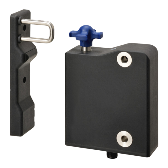
High-Coded Guard Lock Safety Door Switch
D41L
Keep your machines hygienic
• Tamper-proof safety door switch to prevent human error
• Hygienically designed switch
Unique locking mechanism prevents water
and foreign matter from collecting
Smooth surface leaves no wiping unevenness
• Complies with ISO 14119 (Type 4/High Coded),
ISO 13849-1 (PLe)
• ECOLAB certified
Refer to Safety Precautions on page18
Identical mounting for left and right hinged doors
Features
Large actuator tolerances
• Actuator tolerance in
longitudinal direction ± 3.5 mm,
lateral direction ± 2.0 mm
A high-coded safety switch is defined as one where a sensor is paired with a high level coded actuator for which more than 1,000 variations are
available.
±2.0 mm
±3.5 mm
Easy latching force adjustment
• The latching force can be increased
from 25 N to 50 N simply
by turning the star handle 180°.
• Position I: approx. 25 N,
Position II: approx. 50 N
* The actuator is sold separately.
For the most recent information on models that have been certified for
safety standards, refer to your OMRON website.
LED display
• Smart diagnostic
by means of 3-color LED's
• LED red: Fault
LED yellow: Status
LED green: Power
1
Advertisement
Table of Contents

Subscribe to Our Youtube Channel
Related Manuals for Omron D41L

Summary of Contents for Omron D41L
- Page 1 * The actuator is sold separately. For the most recent information on models that have been certified for Refer to Safety Precautions on page18 safety standards, refer to your OMRON website. Identical mounting for left and right hinged doors Features ±2.0 mm...
-
Page 2: Model Number Structure
D41L Model Number Structure Model Number Legend Safety Door Switch Sensor D41L - @ @ D @ @ - N2 (2) (3) (4) (5) (6) (1) Model L: Guard Lock (2) Coding level / Teaching limitation 1: High (Individual coding) -
Page 3: Ordering Information
D41L Ordering Information List of Models Sensors Classification Coding level / Emergency Appearance OSSD configuration Model (Lock and Release) Teaching limitation exit High Only guard monitoring D41L-1ZDA-N2 (Individual coding) High (Individual coding, Only guard monitoring D41L-2ZDA-N2 No limitation) High Guard monitoring AND... -
Page 4: Standards Certification
• UL508 • CAN/CSA C22.2 No.14 Regions where D41L can be used The product can be used in Japan, the United States of America, Canada, EU member states, the United Kingdom, and People's Republic of China. The use in other countries may conflict with radio laws of the countries. -
Page 5: Ratings And Specifications
Transmitter output -6 dBm max. Interlock type (ISO 14119) Type 4 D41L-1: High (individual coding) Coded level (ISO 14119) D41L-2: High (individual coding, No limitation) Actuator D41L-A1 Response time (ON to OFF) 100 ms max. Response time (input) 1.5 ms max. - Page 6 D41L Model D41L Mechanical Protection class Switching frequency 0.5 Hz max. Rated insulation voltage (Ui) 32 VDC Rated impulse withstand voltage (Uimp) 0.8 kV Minimum operating current (Im) 0.5 mA Fixing screws 2 × M6 Tightening torque of fixing screws 6 to 7 N·m...
-
Page 7: Safety Classification Information
2. The safety consideration of the guard locking function only applies for monitored safety door switch D41L-@Y. 3. If for a certain application the power to unlock type of a safety door switch cannot be used, then for this exception the power-to-lock type of a safety door switch can be used if additional safety measure need to be realized that have an equivalent safety level. - Page 8 Structure and Nomenclature Sensor and Actuator Emergency exit (D41L-@@D@E-N2) 1. High degree of protection against defeating due to the coded RFID sensor (also available with individual coding) 2. Dampener for door stop - saves costs: no additional mounting parts required 3.
-
Page 9: Pin Assignment
100 ms and the accepted test pulse duration of at least 1 ms. Also, the cross-wire-short monitoring function must be disabled. D41L series connection example When connecting multiple safety door switches in series, apply 24 VDC to safety inputs X1 and X2 on the Nth unit, as shown in the figure below. - Page 10 Example Example Example Combination with a safety relay unit G9SB G9SX G9SA G9SE OMRON’s safety relay unit Input device D41L Connectable Not connectable Connectable Connectable Safety-door switch * Refer to the instruction manual or user’s manual of each product for how to extend the wiring.
-
Page 11: Manual Release
POWER Manual release Emergency exit (D41L-@@D@E-N2) To activate the emergency exit, turn the red lever in the direction of the arrow to the end stop. The safety outputs switch off and the guard system can be opened. The blocked position is cancelled by turning the lever in the opposite direction. In the unlocked position, the guard system is secured against unintentional locking. - Page 12 When the above procedure is attempted with a D41L-1 which already completed teaching, the teaching procedure will not start. For ordering suffix D41L-2, the teach-in procedure for a new actuator can be repeated an unlimited number of times. When a new actuator is taught, the code, which was applicable until that moment, becomes invalid.
-
Page 13: Operating Principle
In the standard D41L variant, the unlocking of the safety door switch causes the safety outputs to be disabled. The unlocked guard door can be relocked as long as the actuator is inserted in the D41L safety • Normal sequence, door was locked door switch;... - Page 14 D41L Dimensions (Unit: mm) Sensors D41L-@@D@-N2 34 dia. 87.4 17.5 D41L-@@D@E-N2 34 dia. 20.5 87.4 17.5 34.4...
- Page 15 D41L Actuator (Sold separately) D41L-A1 23.4 5 dia. 18.5 16.4 6.7 dia. Accessory (Sold separately) Mounting plate/Mounting Set Mounting plate D41L-MP 18.5...
- Page 16 D41L Mounting Accessories for installation (Mounting plate (D41L-MP)) For the correct fixing of the safety door switch and the actuator, two mounting holes for M6 screws are provided It can be installed by using the following for the type to be installed on (tightening torque: 6 to 7 N•m).
-
Page 17: Troubleshooting
24 V *1 24 V *1 24 V Flashes *2 Error 0 V (24 V) 24 V (0 V) Additionally for variant D41L-1/-2: Teach-in procedure actuator Flashes started Only D41L-2: Tampering Flashes protection time *3 *1. After 30 min: disabling due to fault *2. -
Page 18: Safety Precautions
D41L Safety Precautions Be sure to read the precautions for all models in the website at: http://www.ia.omron.com/. Warning Indications Alert Statements WARNING Indicates a potentially hazardous situation which, if not avoided, will Use only appropriate components or devices result in minor or moderate injury, or... - Page 19 7. Tighten the screws with a specified torque. product. 8. Use the wires specified by OMRON to wire the product. 33.Install the product to a position near a handle of the guard door. (Refer to Connection.) Installing it near a hinge may cause the locking part of the product 9.
-
Page 20: Maintenance
D41L Set-up and Maintenance/Disassembly and Disposal Set-up and Maintenance Disassembly and Disposal Disassembly Functional testing The product must be disassembled in a de-energized condition only. The safety function of the safety components must be tested. The following conditions must be previously checked and met: Disposal 1. -
Page 21: Terms And Conditions Agreement
Return of any Products by Buyer must be approved in writing by Omron before shipment. Omron Companies shall not be liable for the suitability or unsuitability or the results from the use of Products in combination with any electrical or electronic components, circuits, system assemblies or any other materials or substances or environments. - Page 22 For the most recent information on models that have been certified for Refer to Safety Precautions on page 17 safety standards, refer to your OMRON website. For the most recent information on models that have been certified for Refer to Safety Precautions on page18 safety standards, refer to your OMRON website.
Need help?
Do you have a question about the D41L and is the answer not in the manual?
Questions and answers