Thermador CEM456 Service Manual
Hide thumbs
Also See for CEM456:
- Care and use manual (16 pages) ,
- Use and care manual (40 pages) ,
- Installation instructions manual (20 pages)
Table of Contents
Advertisement
OFF
OFF
OFF
OFF
LO
HI
HI
HI
HI
HI
HI
HI
LO
LO
LO
LO
LO
LO
MED
OFF
OFF
HI
HI
HI
LO
HOT SURFACE
ON
LO
LO
MED
CEM456
OFF
OFF
OFF
HI
HI
HI
HI
HI
HI
LO
LO
LO
LO
LO
LO
OFF
OFF
HI
HI
LO
LO
HOT SURFACE
ON
MED
MED
CEM365
OFF
OFF
HI
HI
HI
HI
LO
LO
LO
LO
OFF
OFF
HI
LO
HI
LO
HOT SURFACE
ON
MED
MED
CEM304
Service Manual
CEM/CET/CEP COOKTOPS
© 2002 BSH Home Appliances Corp.
CEP365 • CET365
CEP304 • CET304
for
®
5
4
6
PANEL
3
7
LOCK
2
PAN
8
ZONE
SIZE
SMART™
1
9
POWER
KEEP
WARM
CEP456
5
4
6
PANEL
LOCK
3
7
PAN
ZONE
2
8
SIZE
SMART™
1
9
POWER
KEEP
WARM
5
4
6
PANEL
3
LOCK
7
2
PAN
8
ZONE
SIZE
SMART™
1
9
POWER
KEEP
WARM
Advertisement
Table of Contents

Related Manuals for Thermador CEM456


Summary of Contents for Thermador CEM456
- Page 1 ® HOT SURFACE PANEL LOCK ZONE SIZE SMART™ POWER KEEP WARM CEM456 CEP456 PANEL LOCK ZONE SIZE SMART™ HOT SURFACE POWER KEEP WARM CEM365 CEP365 • CET365 PANEL LOCK ZONE SIZE SMART™ HOT SURFACE POWER KEEP WARM CEM304 CEP304 • CET304...
-
Page 2: Table Of Contents
Table of Contents Cooktop Models ..........1 - 2 Component Description ........14 CEM Cooktops ............3 Electronic Touch Control Board ...... 15 CET Cooktops: ............4 Component Description ........15 CEP Cooktops: ............5 Relay board ............16 Ceramic Cooktop Technical Overview ..... 6 Component Description ........ -
Page 3: Cooktop Models
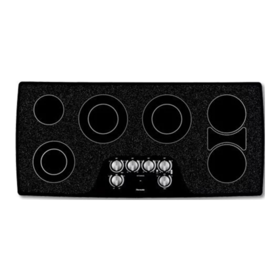
CEM/CET/CEP Service Manual Cooktop Models Cooktop Models HOT SURFACE HOT SURFACE CEM304 CEM365 HOT SURFACE CEM456 TYPE SIZE WATTAGE Single 6" (140 mm) 1200 W Double 5"/8" (120/210 mm) 750 / 2200 W Double 7"/8"(140/230 mm) 1100 / 2500 W Single 7"... - Page 4 CEM/CET/CEP Service Manual Cooktop Models Cooktop Models PANEL LOCK PANEL LOCK ZONE SIZE SMART™ ZONE SIZE SMART™ POWER POWER KEEP WARM KEEP WARM CET304 CET365 CEP304 CEP365 PANEL LOCK ZONE SIZE SMART™ POWER KEEP WARM CEP456 TYPE SIZE WATTAGE Single 6"...
-
Page 5: Cem Cooktops
The cooktop is connected to 240 volts. All components are activated by 240 volts. There is no neutral line, only l1, l2, and ground. HOT SURFACE HOT SURFACE CEM304 CEM365 HOT SURFACE CEM456 PAGE 3... -
Page 6: Cet Cooktops
CEM/CET/CEP Service Manual Cooktop Models CET Cooktops: The CET cooktop has a touch sensitive mono-control system. By touching the pads on the ceramic top, you select the mode of operation and the desired power level. The electronic touch control board interprets the selection and activates the single, dual, triple and bridge elements. -
Page 7: Cep Cooktops
CEM/CET/CEP Service Manual Cooktop Models CEP Cooktops: The CEP cooktop incorporates all the features of the cet cooktop plus zone smart. Zone smart senses the presence of cookware and selects the most appropriate sized element. Additionally, it turns the element off when the pan is removed. -
Page 8: Ceramic Cooktop Technical Overview
CEM/CET/CEP Service Manual Technical Overview Ceramic Cooktop Technical Overview The CEM/CET/CEP cooktops are comprised of the following components: Radiant Elements Single Elements Dual Elements Triple Elements Radiant Bridge Elements Infinite Switches 1-Cycle 2-Cycle Control Knobs Relay Board Electronic Touch Control Relay Board Pot Sensing Circuit Board Heat Limiters Sensors... -
Page 9: Component Description
CEM/CET/CEP Service Manual Component Description Component Description Radiant Elements A single element, illustration above, uses a wire ribbon that is located under the glass ceramic surface to provide the heat for cooking. The single element uses 1 wire ribbon. Radiant elements are designed to cycle on and off. -
Page 10: Radiant Elements
CEM/CET/CEP Service Manual Component Description Radiant Elements The triple element, illustration above, uses 3 wire ribbons to provide heat for cooking. There are 3 ribbons within the same heating area. You can select the inner, the inner and middle, or the inner, middle and outer elements. -
Page 11: Infinite Switches
CEM/CET/CEP Service Manual Component Description Infinite Switches There is 2 types of infinite switches. 1-cycle, and 2 cycle. The 1-cycle infinite switch controls the single element. The 1-cycle has an infinite number of heat settings between the low and high positions. Detents are found at low and high to define minimum and maximan heat settings. -
Page 12: Relay Board
CEM/CET/CEP Service Manual Component Description Relay board A relay board and a 2-cycle infinite switch are used to operate the bridge elements. The bridge element (4000 watts) draws 16 amps at full capacity. The 2-cycle infinite switch is rated at about 10 amps. The relay is wired in series with the infinite switch and the bridge element. -
Page 13: Temperature Limiters
CEM/CET/CEP Service Manual Component Description Temperature limiters Each element uses a temperature limiter to prevent the element from becoming too hot. The limiters have 2 sets of contacts, one is normally open, and one is normally closed. The normally open contact closes and turns on the hot surface light when the glass is too hot to touch. -
Page 14: Indicator Lights
CEM/CET/CEP Service Manual Component Description Indicator lights There are two indicator lights on the ceramic cooktops. The ON indicator light turns on whenever any element is turned on. The light remains on until all the elements are turned off. (see illustration) Each element features a hot indicator light circuit to show when the cooking surface is too hot to touch. -
Page 15: Sensors
CEM/CET/CEP Service Manual Component Description Sensors: On CEP models the sensors detect pan sensing and pan sizing. Pan sensing: The CEP models have sensors under the glass that detects if there is a metallic pan sitting on the element. The element will not heat if it is turned on without a pan present, or if the pan is removed from the element when it is operating. -
Page 16: Pot Sensing Circuit Board
CEM/CET/CEP Service Manual Component Description Pot Sensing Circuit Board The pot sensing circuit board works with the electronic touch control board to sense the presence and the size of a pan on the burner. Heres how it works: The input board sends a signal to the sensor in each of the elements. When a pan is placed on the element,the sensor sends a signal back to the input board. -
Page 17: Electronic Touch Control Board
CEM/CET/CEP Service Manual Component Description Electronic Touch Control Board The electronic touch control board is a microproccessor based control. It is comprised of 2 components, an input board, and a relay board. These 2 components are fastened together with stand off clips. There is a mylar sheet sandwiched between the 2 components. -
Page 18: Relay Board
CEM/CET/CEP Service Manual Component Description Relay board The relay board has snap relays, a step down transformer, a microproccessor chip and several zenner diodes. The stepdown transformer receives 120 v.a.c. and steps it down to 12 v.a.c.. The zenner diodes rectify the 12 v.a.c. -
Page 19: Input Board
CEM/CET/CEP Service Manual Component Description Input board The input board has three functions. First, it accepts mode and setting selections by the user. Second, it commands the relay board to perform the selected functions. And third, it outputs a signal voltage circuit to the element sensors to determine the presence of a pan , and the size of the pan. -
Page 20: Installation
Spread)/(Smoke Developed)”. Materials with “O” requirements: Model CEM304 at 30 Amps; Model flame spread ratings are flame retardant. Local codes CEM365 at 40 Amps or Model CEM456 at 50 Amps may allow other flame spread ratings. Install a junction box (not supplied), below the... - Page 21 CEM/CET/CEP Service Manual Cooktop Dimensions CEM304 " / (505 mm) 20" / (508 mm) " / (731 mm) " / (734 mm) CEM365 " / (505 mm) 20" / (508 mm) " / (883 mm) " / (886 mm) CEM365 "...
- Page 22 Place cooktop into cutout. Insert clamping screw into the bracket and secure cooktop to countertop. NOTE: Thermador single oven Models S301, SC301, C301 and CM 301 installed under-the-counter with Use a wood block to protect fragile countertop ®...
- Page 23 CEM/CET/CEP Service Manual Cooktop Installation PAGE 21...
-
Page 24: Cet/Cep Cooktops Installation
Spread)/(Smoke Developed)”. Materials with “O” requirements: Model CEM304 at 30 Amps; Model flame spread ratings are flame retardant. Local codes CEM365 at 40 Amps or Model CEM456 at 50 Amps may allow other flame spread ratings. Install a junction box (not supplied), below the... - Page 25 CEM/CET/CEP Service Manual Cooktop Installation CET304 " / (505 mm) 20" / (508 mm) CEP304 " / (731 mm) " / (734 mm) CET365 " / (505 mm) 20" / (508 mm) CEP365 " / (883 mm) " / (886 mm) CEP456 "...
- Page 26 Place cooktop into cutout. Insert clamping screw into the bracket and secure cooktop to countertop. NOTE: Thermador single oven Models S301, SC301, C301 and CM 301 installed under-the-counter with Use a wood block to protect fragile countertop ®...
- Page 27 CEM/CET/CEP Service Manual Cooktop Installation PAGE 25...
-
Page 28: Cooktop Disassembly
CEM/CET/CEP Service Manual Cooktop Disassembly Disassembly Uninstall and flip the cooktop over so the main top faces down. Remove the T20 screws then lift the base off. PAGE 26... - Page 29 CEM/CET/CEP Service Manual Cooktop Disassembly Disassembly After the screws are removed, lift off the bottom. CEP Bottom Off PAGE 27...
- Page 30 CEM/CET/CEP Service Manual Cooktop Disassembly Disassembly Element Removal Remove T20 screw from brace. PAGE 28...
- Page 31 CEM/CET/CEP Service Manual Cooktop Disassembly Disassembly Element Removal Mark the spring location with a magic marker. Loosen T20 screw to remove element. PAGE 29...
- Page 32 CEM/CET/CEP Service Manual Cooktop Disassembly Disassembly Control Board Removal 2. Remove supports by lifting up and off. 1. Remove T20 Screws 3. Press in the clips. 4. Raise the wire blocks out of the frame. PAGE 30...
- Page 33 CEM/CET/CEP Service Manual Cooktop Disassembly Disassembly Control Board Removal 5. Lift out the control module. PAGE 31...
- Page 34 CEM/CET/CEP Service Manual Cooktop Disassembly Disassembly Mechanical Module PAGE 32...
-
Page 35: Cooktop Reassembly
Cooktop Reassembly CEM/CET/CEP Service Manual Reassembly Install the center screw first, then install remaining screws. PAGE 33... -
Page 36: Technical Data - Table Of Errors
CEM/CET/CEP Service Manual Technical Data Technical Data Table of Error Messages The error message will show on the display clockwise. The assign between display and digit is dependend of the cooktop variants. Display Name Meaning The data that is transmitted to the shift registers to control the relays and the fan is watched permanently. -
Page 37: Cet/Cep Residual Heat On Time
CEM/CET/CEP Service Manual Technical Data Technical Data Residual Heat on Time CET/CEP • • • • • • • minute minutes minutes minutes minutes minutes minutes Element ON Time Zone ON Time Setting Residual Heat Indocator ON Time 1 minute ..........32 minutes 2 minutes ..........36 minutes 5 minutes ..........46 minutes 10 minutes .......... -
Page 38: Pot Sensing Calibration
CEM/CET/CEP Service Manual Pot Sensing Calibration Pot Sensing Calibration CEP models have the “Zone Smart” (Pot Sensing) feature, and must be calibrated, or recalibrated, whenever the Electronic Control is replaced. To calibrate the cooktop, the “P7” Menu must be accessed, followed by the “P8” Menu. A set of calibration plates, each having a specific size, weight, and material, must be placed on their appropriate element locations during the calibration procedure. - Page 39 CEM/CET/CEP Service Manual Pot Sensing Quick Calibration POT SENSING QUICK CALIBRATION I. Touch and hold the POWER and LF (Left Front) element pads. The display will quickly flash a series of dashes. Immediately release only the LF (Left Front) element pad. The dashes on the display should now remain on continuously.
- Page 40 CEM/CET/CEP Service Manual Pot Sensing Quick Calibration 5. Simultaneously touch the ZONE SMART pad and the number “3” Heat Setting pad and then release both pads. A flashing “U” will appear in the display. The unit will beep, and “P8U” will flash in the display. 6.
- Page 41 CEM/CET/CEP Service Manual Pot Sensing Quick Calibration 7. Simultaneously touch the ZONE SMART pad and the number “4” Heat Setting pad, then release the pads. A flashing “U” will appear in the display. When a beep sounds, the unit is properly calibrated. 8.
-
Page 42: Wiring And Visuals
CEM/CET/CEP Service Manual Wiring and Visuals Wiring and Visuals PAGE 40... - Page 43 CEM/CET/CEP Service Manual Wiring and Visuals PAGE 41...
- Page 44 CEM/CET/CEP Service Manual Wiring and Visuals PAGE 42...
- Page 45 CEM/CET/CEP Service Manual Wiring and Visuals PAGE 43...
- Page 46 CEM/CET/CEP Service Manual Wiring and Visuals PAGE 44...
- Page 47 CEM/CET/CEP Service Manual Wiring and Visuals PAGE 45...
- Page 48 CEM/CET/CEP Service Manual Wiring and Visuals PAGE 46...
- Page 49 CEM/CET/CEP Service Manual Wiring and Visuals PAGE 47...
- Page 50 CEM/CET/CEP Service Manual Wiring and Visuals PAGE 48...
- Page 51 CEM/CET/CEP Service Manual Wiring and Visuals PAGE 49...
- Page 52 CEM/CET/CEP Service Manual Wiring and Visuals PAGE 50...
- Page 53 CEM/CET/CEP Service Manual Wiring and Visuals PAGE 51...
- Page 54 CEM/CET/CEP Service Manual Wiring and Visuals PAGE 52...
- Page 55 CEM/CET/CEP Service Manual Wiring and Visuals PAGE 53...
- Page 56 CEM/CET/CEP Service Manual Wiring and Visuals PAGE 54...
- Page 57 CEM/CET/CEP Service Manual Wiring and Visuals PAGE 55...
- Page 58 CEM/CET/CEP Service Manual Wiring and Visuals Wiring Diagram CEP 30" Element Harness Element Harness DOC#:5060000000 Station 3 Date: 09/05/01 Rev: A ECO#: PAGE 56...
- Page 59 CEM/CET/CEP Service Manual Wiring and Visuals Wiring Diagram CEP 30" Power Harness Power Harness DOC#:5060000000 Station 3 Date: 09/05/01 Rev: A ECO#: PAGE 57...
- Page 60 CEM/CET/CEP Service Manual Wiring and Visuals PAGE 58...
- Page 61 CEM/CET/CEP Service Manual Wiring and Visuals PAGE 59...
- Page 62 CEM/CET/CEP Service Manual Wiring and Visuals PAGE 60...
- Page 63 CEM/CET/CEP Service Manual Wiring and Visuals Wiring Diagram CEP 36" Power Harness Note: This wire will be changed to a blue wire. DOC#:5060000000 Station 3 Date: 09/12/01 Rev: A ECO#: PAGE 61...
- Page 64 CEM/CET/CEP Service Manual Wiring and Visuals Wiring Diagram CEP 36" Power Harness Note: This wire will be changed to a blue wire. DOC#:5060000000 Station 3 Date: 09/12/01 Rev: A ECO#: PAGE 62...
- Page 65 CEM/CET/CEP Service Manual Wiring and Visuals PAGE 63...
- Page 66 CEM/CET/CEP Service Manual Wiring and Visuals Wiring Diagram CET 30" (Power Harness) Power Harness DOC#:5060000000 Station 3 Date: 08/30/01 Rev: A ECO#: PAGE 64...
- Page 67 CEM/CET/CEP Service Manual Wiring and Visuals PAGE 65...
- Page 68 CEM/CET/CEP Service Manual Wiring and Visuals PAGE 66...
- Page 69 CEM/CET/CEP Service Manual Wiring and Visuals Wiring Diagram CET 30" (Element Harness) Element Harness DOC#:5060000000 Station 3 Date: 08/30/01 Rev: A ECO#: PAGE 67...
- Page 70 CEM/CET/CEP Service Manual Wiring and Visuals PAGE 68...
- Page 71 CEM/CET/CEP Service Manual Wiring and Visuals PAGE 69...
-
Page 72: Electrical Schematic Drawings
CEM/CET/CEP Service Manual Wiring and Visuals Electrical Schematic Drawing CET/CEP 365 PAGE 70... -
Page 73: Cet/Cep 304
CEM/CET/CEP Service Manual Wiring and Visuals Electrical Schematic Drawing CET/CEP 304 PAGE 71... -
Page 74: Cem 456
CEM/CET/CEP Service Manual Wiring and Visuals Electrical Schematic Drawing CEM 456 PAGE 72... -
Page 75: Cem 304
CEM/CET/CEP Service Manual Wiring and Visuals Electrical Schematic Drawing CEM 304 PAGE 73... -
Page 76: Cem 365
CEM/CET/CEP Service Manual Wiring and Visuals Electrical Schematic Drawing CEM 365 PAGE 74... - Page 77 CEM/CET/CEP Service Manual Wiring and Visuals Notes...
- Page 78 CEM/CET/CEP Service Manual Wiring and Visuals Notes...
- Page 79 CEM/CET/CEP Service Manual Wiring and Visuals Notes...
- Page 80 ® 5551 McFadden Avenue, Huntington Beach, CA 92649 • 800/735-4328 5060008355 • © 2002 BSH Home Appliances, Corp. • Litho in U. S. A. 11/02...
Need help?
Do you have a question about the CEM456 and is the answer not in the manual?
Questions and answers