Table of Contents
Advertisement
Quick Links
Advertisement
Table of Contents

Related Manuals for BZB Gear BG-UHD-VW24


Summary of Contents for BZB Gear BG-UHD-VW24
- Page 1 BG-UHD-VW24 Ultra HD Video Wall Processor...
-
Page 2: Table Of Contents
Thank you for purchasing the BG-UHD-VW24 Please read the instructions carefully before connecting, operating, or configuring this product. Please save this manual for future reference. Surge Protection Recommendation This product contains sensitive electrical components that may be damaged by electrical spikes, surges, electric shock, lighting strikes, etc. -
Page 3: Introduction
1. Introduction The BG-UHD-VW24 is a HDMI 2.0 Video Wall controller with 2 HDMI inputs, 2 HDMI loop outs and 4 HDMI scaling outputs for video wall processing. The 5-pin phoenix connector provides balanced L/R audio output. The product also features PC Tool or RS232 commands to control the product for different wall displays. -
Page 4: Specifications
4. Specifications Technical HDMI Compliance HDMI 2.0 HDCP Compliance HDCP 2.2/1.4 RS-232 Baud rate: 57600, data bit: 8, Stop bit: 1, no parity 4096x2160p 24/25/30/50/60Hz 1400x1050 60Hz 3840x2160p 24/25/30/50/60Hz 1366x768 60Hz 1080p 24/25/30/50/60Hz 1360x768 60Hz 1080i 50/60Hz 1280x1024 60Hz Input Video Formats 1920x1200 60Hz 1280x960 60Hz 1680x1050 60Hz... -
Page 5: Operation Controls And Functions
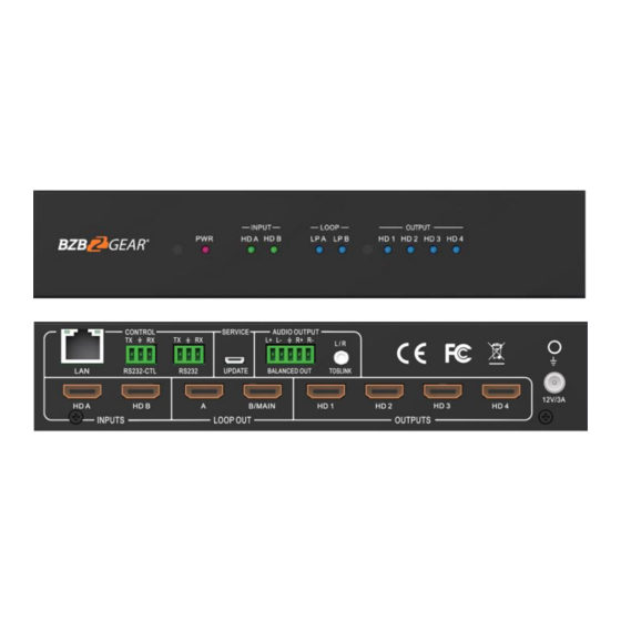
5. Operation Controls and Functions Front Panel Name Function Description The power LED will illuminate when the unit is powered on. Power LED The LED will illuminate when the corresponding HDMI input port is INPUT LED connected to an active HDMI source device. The LED will illuminate when the corresponding LOOP OUT port LOOP LED is connected to an HDMI display device. -
Page 6: Rs232/Lan Control Connection
Analog L/R audio output • 3.5mm Stereo Jack. 20Hz ~ 20kHz, 1.5Vrms max AUDIO OUTPUT BALANCED OUT: Balanced audio output port. 5-pin phoenix connector, 20Hz ~ 20kHz, 1.5Vrms max. SERVICE Firmware update port. RS232: Loop out RS232-CTL control command. RS232-CTL: External RS232 control, Baud Rate: 57600 Data Bits:8, Parity: None Stop Bits:1 CONTROL LAN: Network port for TCP/IP control. -
Page 7: Pc Tool User Guide
7. PC Tool User Guide The PC Tool control software supports both UART and network control. PC Tool consists of five parts: Matrix Switch, Signal Setting, Fine Tune: PQ, Video Wall and CEC Control. The UI is as follows: ■ Matrix Switch Tab 1. - Page 8 The available predefined EDID options: 1920x1200-2.0CH 4K60-2.0CH 1680x1050-2.0CH 4K60-5.1CH 4K30-2.0CH 1600x1200-2.0CH 4K30-5.1CH 1440x900-2.0CH 1400x1050-2.0CH 1080P-2.0CH 1360x768-2.0CH 1080P-5.1CH 1280x1024-2.0CH 720P-2.0CH Manual 1024x768-2.0CH ■ Signal Setting Tab The resolution of each input can be read to configure the resolution of each output. Available output resolutions: Output Resolution Setting Output Resolution Setting...
- Page 9 ■ FineTune:PQ Tab Configure the brightness, contrast, saturation, and sharpness of each output. Note: The recommended settings are the default 50/50/50/50. Please do not change the default settings unless under special circumstances. If problems arise after reconfiguration, click ‘Reset’ to return to default settings. ■...
- Page 10 ■ Video Wall Tab Configure a group of outputs to function together as a video wall. The Video Wall Setting controls manage how the displays are arranged: Adjust the “Rows” and “Columns” sliders to adjust the displayed screens arrangement. The “Available” slider sets the number screens that will be used for the Video Wall.
- Page 11 Creating a second video wall: Repeat steps 2-5 above using a different set out outputs. Please note that changing the “Rows”, “Columns” and “Available” sliders will automatically delete the current video wall configuration once the “Set” button is clicked. The following example shows an unusual video wall configuration for demonstrative purposes.
- Page 12 Screen Splicing This option connects the selected screens into a video wall configuration. Cancel Splicing Return the Video Wall configuration to normal outputs. Remove a single screen from the unified video wall to display a separate image. See the example below: Screen 2 –...
- Page 13 Bezel Setting The Bezel Setting allows for the adjustment of the images displayed on the video wall to compensate for the thickness of the TV’s bezel. The displays on the video wall should create a cohesive, unified image. To achieve this, the edge of each display’s image must be removed from the sides of displays that meet.
-
Page 14: Safety Instructions
8. Safety Instructions To ensure reliable operation of this product as well as protecting the safety of any person using or handling this device while powered, please observe the following instructions. 1. Do not operate this product outside the specified temperature and humidity range given in the above specifications. -
Page 15: Connection Diagram
9. Connection Diagram Speakers Control System DVD Player Lap Top TV ×4 HDMI AUDIO 10. Tech Support Before contacting tech support, we may have answered your question already! Visit our BZBGEAR support page at bzbgear.com/support for valuable information on our products. Here you will find our Knowledge Base (bzbgear.com/knowledge-base) consisting of tutorials, quick start guides, and step-by-step troubleshooting instructions. -
Page 16: Warranty
11. Warranty BZBGEAR Pro AV products and Cameras come with a three-year warranty. An extended two-year warranty is available for our Cameras upon registration for a total of five years. For an extended two-year warranty on our Cameras, follow these steps: 1.
Need help?
Do you have a question about the BG-UHD-VW24 and is the answer not in the manual?
Questions and answers