
Related Manuals for Agilent Technologies LC Series


Summary of Contents for Agilent Technologies LC Series
- Page 1 1290 Infinity II Valve Drive and Valve Heads Agilent InfinityLab LC Series User Manual 1290 Infinity II Valve Drive and Valve Heads User Manual...
- Page 2 CAUTION beyond a notice until ble for errors or for incidental or conse- sent from Agilent Technologies, Inc. as the indicated conditions are fully governed by United States and interna- quential damages in connection with the understood and met.
- Page 3 In This Guide… This manual covers the following: • Agilent InfinityLab LC Series 1290 Infinity II Valve Drive (G1170A) • Agilent InfinityLab Quick Change Valves Introduction to the Agilent 1290 Infinity II Valve Drive and InfinityLab LC Series Valves This chapter gives an introduction to the module, instrument overview and internal...
- Page 4 Maintenance This chapter gives you an overview and instructions about the possible maintenance and repair procedures that can be performed by the user. Parts and Materials This chapter provides information on parts and materials. Identifying Cables This chapter provides information on cables used with the Agilent Infinity and Infinity II Series modules.
-
Page 5: Table Of Contents
Contents Introduction to the Agilent 1290 Infinity II Valve Drive and InfinityLab LC Series Valves Overview of the Valve Drive Overview of the Agilent InfinityLab Quick Change Valves Typical Applications Leak and Waste Handling Site Requirements and Specifications Site Requirements Physical Specifications Performance Specifications Installing the Module... - Page 6 Error Information What Are Error Messages General Error Messages Module Specific Error Messages Maintenance Introduction to Maintenance Cautions and Warnings Overview of Maintenance Cleaning the Module Replacing Parts of the Valve Head Replacing the Fuses of the Infinity II Valve Drive Replacing Valve Heads Replacing the Module Firmware Parts and Materials...
- Page 7 Config Switch Settings of the Infinity II Valve Drive Appendix General Safety Information Waste Electrical and Electronic Equipment (WEEE) Directive Radio Interference Sound Emission Solvent Information Agilent Technologies on Internet 1290 Infinity II Valve Drive and Valve Heads User Manual...
-
Page 8: Introduction To The Agilent 1290 Infinity Ii Valve Drive And Infinitylab Lc Series Valves
Introduction to the Agilent 1290 Infinity II Valve Drive and InfinityLab LC Series Valves Overview of the Valve Drive Overview of the Agilent InfinityLab Quick Change Valves Typical Applications Dual and Multiple Column Selection Sample Enrichment and Sample Cleanup Alternating Column Regeneration... -
Page 9: Overview Of The Valve Drive
Introduction to the Agilent 1290 Infinity II Valve Drive and InfinityLab LC Series Valves Overview of the Valve Drive Overview of the Valve Drive The Agilent 1290 Infinity II Valve Drive (G1170A) is a part of the InfinityLab LC Series. This is a valve drive delivered without a specific valve head. To be used in a HPLC system it is required to add a valve head to this device. - Page 10 Introduction to the Agilent 1290 Infinity II Valve Drive and InfinityLab LC Series Valves Overview of the Valve Drive Figure 1 Mounting Examples for 1290 Infinity II Valve Drive 1290 Infinity II Valve Drive and Valve Heads User Manual...
- Page 11 Introduction to the Agilent 1290 Infinity II Valve Drive and InfinityLab LC Series Valves Overview of the Valve Drive Clamps (attachable to both sides) Valve Drive Status indicator Changeable valve head Leak sensor Attachable leak plane Figure 2 Overview of 1290 Infinity II Valve Drive...
- Page 12 Introduction to the Agilent 1290 Infinity II Valve Drive and InfinityLab LC Series Valves Overview of the Valve Drive Fuses External leak sensor connector Config switch CAN ports Power switch Power connector Figure 3 Rear View of 1290 Infinity II Valve Drive...
-
Page 13: Overview Of The Agilent Infinitylab Quick Change Valves
Introduction to the Agilent 1290 Infinity II Valve Drive and InfinityLab LC Series Valves Overview of the Agilent InfinityLab Quick Change Valves Overview of the Agilent InfinityLab Quick Change Valves The Agilent InfinityLab Quick Change Valves can be installed in the Multicolumn Thermostat (G7116A/B), the 1290 Infinity Flexible Cube (G4227A) and in the 1290 Infinity II Valve Drive (G1170A). - Page 14 Introduction to the Agilent 1290 Infinity II Valve Drive and InfinityLab LC Series Valves Overview of the Agilent InfinityLab Quick Change Valves Table 1 Overview of the available Agilent Quick Change Valve Kits Valve Kit PN Pressure Positions Ports Typical Application...
-
Page 15: Typical Applications
Introduction to the Agilent 1290 Infinity II Valve Drive and InfinityLab LC Series Valves Typical Applications Typical Applications Agilent InfinityLab Quick Change Valves support a variety of valve applications. They can be mounted to an external 1290 Infinity II Valve Drive (G1170A) or a Multicolumn Thermostat (G7116A/B). - Page 16 Introduction to the Agilent 1290 Infinity II Valve Drive and InfinityLab LC Series Valves Typical Applications Multiple Column Selection With the 6-column selection valve (G4234A/C) and the capillary kit for column selection you can set up your system for use with up to 6 columns as displayed Figure 4 on page 16.
-
Page 17: Sample Enrichment And Sample Cleanup
Introduction to the Agilent 1290 Infinity II Valve Drive and InfinityLab LC Series Valves Typical Applications Sample Enrichment and Sample Cleanup Sample Enrichment Pump A / autosampler Pump A / autosampler Analytical Analytical column / column / detector detector Waste... - Page 18 Introduction to the Agilent 1290 Infinity II Valve Drive and InfinityLab LC Series Valves Typical Applications Advantages: • Easy automation of sample preparation • Higher reproducibility • Increased productivity and sensitivity Sample cleanup is essential for samples with complex matrices, such as food extracts and waste water.
-
Page 19: Alternating Column Regeneration
Introduction to the Agilent 1290 Infinity II Valve Drive and InfinityLab LC Series Valves Typical Applications Alternating Column Regeneration Advantages: • High sample throughput • Increased productivity • High efficiency Column 2 Column 2 Eluent pump / Eluent pump /... -
Page 20: Solvent Selection
Introduction to the Agilent 1290 Infinity II Valve Drive and InfinityLab LC Series Valves Typical Applications Solvent Selection The 12-position/13-port solvent selection valve (G4235A) can be used for solvent selection (flow rate < 10 mL/min) as illustrated in Figure 5 on page 20. -
Page 21: Leak And Waste Handling
Introduction to the Agilent 1290 Infinity II Valve Drive and InfinityLab LC Series Valves Leak and Waste Handling Leak and Waste Handling The Agilent InfinityLab LC Series has been designed for safe leak and waste handling. It is important that all security concepts are understood and instructions are carefully followed. - Page 22 Introduction to the Agilent 1290 Infinity II Valve Drive and InfinityLab LC Series Valves Leak and Waste Handling Figure 6 Infinity II Leak Waste Concept (Flex Bench installation) 1290 Infinity II Valve Drive and Valve Heads User Manual...
- Page 23 Introduction to the Agilent 1290 Infinity II Valve Drive and InfinityLab LC Series Valves Leak and Waste Handling Figure 7 Infinity II Single Stack Leak Waste Concept (bench installation) 1290 Infinity II Valve Drive and Valve Heads User Manual...
- Page 24 Introduction to the Agilent 1290 Infinity II Valve Drive and InfinityLab LC Series Valves Leak and Waste Handling Figure 8 Infinity II Two Stack Leak Waste Concept (bench installation) The waste tube connected to the leak plane outlet on each of the bottom instruments guides the solvent to a suitable waste container.
-
Page 25: Leak Sensor
Introduction to the Agilent 1290 Infinity II Valve Drive and InfinityLab LC Series Valves Leak and Waste Handling Leak Sensor Solvent incompatibility C AU T I O N The solvent DMF (dimethylformamide) leads to corrosion of the leak sensor. The material of the leak sensor, PVDF (polyvinylidene fluoride), is incompatible with DMF. -
Page 26: Site Requirements And Specifications
Site Requirements and Specifications Site Requirements Physical Specifications Performance Specifications This chapter provides information on environmental requirements, physical and performance specifications. 1290 Infinity II Valve Drive and Valve Heads User Manual... -
Page 27: Site Requirements
Site Requirements and Specifications Site Requirements Site Requirements A suitable environment is important to ensure optimal performance of the instrument. Power Considerations The module power supply has wide ranging capability. It accepts any line voltage in the range described in Table 2 on page 30. - Page 28 Never use a power cord other than the one that Agilent shipped with this instrument. Never use the power cords that Agilent Technologies supplies with this instrument for any other equipment. Never use cables other than the ones supplied by Agilent Technologies ...
- Page 29 Site Requirements and Specifications Site Requirements Bench Space The module dimensions and weight (see Table 2 on page 30) allow you to place the module on almost any desk or laboratory bench. It needs an additional 2.5 cm (1.0 inches) of space on either side and approximately 8 cm (3.1 inches) in the rear for air circulation and electric connections.
-
Page 30: Physical Specifications
Site Requirements and Specifications Physical Specifications Physical Specifications Table 2 Physical Specifications Type Specification Comments Weight 1.9 kg (4.3 lbs) Dimensions (height × width × 90 x 90 x 300 mm depth) (3.54 x 3.54 x 11.8 inches) Line voltage 100 –... -
Page 31: Performance Specifications
Site Requirements and Specifications Performance Specifications Performance Specifications Table 3 Specifications Agilent InfinityLab Quick Change Valves Kit PN Valve PN Description max. Fittings Liquid pH Range Pressure [bar] Contact G5641A 5067-6682 2-position/10-port valve head, bio 1300 10-32 PEEK, 0-14 MP35N G4231A 5067-4282 2-position/6-port valve head... -
Page 32: Installing The Module
Installing the Module Unpacking the Module Installing the Valve Drive Installing the Valve Heads This chapter gives information about the installation of the valve drive and the valve heads. 1290 Infinity II Valve Drive and Valve Heads User Manual... -
Page 33: Unpacking The Module
Installing the Module Unpacking the Module Unpacking the Module Damaged Packaging If the delivery packaging shows signs of external damage, please call your Agilent Technologies sales and service office immediately. Inform your service representative that the instrument may have been damaged during shipment. "Defective on arrival"... - Page 34 For parts identification please check the illustrated parts breakdown in “Valve Drive Parts” on page 101. Please report any missing or damaged parts to your local Agilent Technologies sales and service office. Table 4 Delivery Checklist Description...
-
Page 35: Installing The Valve Drive
It can be attached to either side of your instrument with the use of the Valve Rail (InfinityLab LC Series, 1260 and 1290 Series Pumps and Detectors, for older modules order new cover kits), or it can be mounted to a G1383A column organizer by using the optional column stand mount. - Page 36 Installing the Module Installing the Valve Drive Assembling and Installing the Leak Tray and Leak Sensor Only connect or disconnect the leak sensor while the valve drive is powered off. NOTE The valve drive must be ‘powered off’ for at least 10 s to recognize any hardware changes correctly.
- Page 37 Installing the Module Installing the Valve Drive Slide the second clamp on to the same side as the first Connect the leak sensor cable to the valve drive. one. Attach the waste tubing to the leak plane and guide it to a proper waste container.
- Page 38 Installing the Module Installing the Valve Drive Mounting the Valve Drive to an Instrument by Using a Valve Rail "Defective on arrival" problems C AU T I O N If there are signs of damage, please do not attempt to install the module. Inspection by Agilent is required to evaluate if the instrument is in good condition or damaged.
- Page 39 Installing the Module Installing the Valve Drive Slide the first clamp on to one side of the valve drive Install the leak tray and leak sensor to the valve. housing. Slide the second clamp on to the same side as the first Slide the valve on to the valve rail.
- Page 40 Installing the Module Installing the Valve Drive Attach the waste tubing to the leak plane and guide it to Connect the power cable to the power connector at the a proper waste container. rear of the module. Connect the CAN interface connection. 10 Power on the module by switching the Power button at the rear of the module if a valve head has been already installed.
- Page 41 Installing the Module Installing the Valve Drive Mounting the Valve Drive to a G1383A Column Organizer For more information about the column organizer read the G1383-90011 Column NOTE Organizer Quick Reference Guide 1 Attach the column stand mount to the column organizer. 2 Attach both clamps to one side of the valve drive.
- Page 42 Installing the Module Installing the Valve Drive Mounting the Valve Drive as a Part of Online Sample Manager Parts required Description G3167-42000 Single Holder UVD Multi Function 0515-5869 Screw-Tapping Pan-HD Hexalobular-Recess 5063-6527 Tubing, Silicon Rubber, 1.2 m, ID/OD 6/9 mm Preparations Ensure the power switch at the rear of the module is off and the power connector is unplugged.
- Page 43 Installing the Module Installing the Valve Drive Mounting the Valve Drive to an Infinity II Module (except Multicolumn Thermostat) Parts required Description 5067-5685 Clamp Guide Kit-IF-II Ensure the power switch at the rear of the module is Identify the marks for the screws on the side of the OFF and the power connector is unplugged.
- Page 44 Installing the Module Installing the Valve Drive Slide the second clamp on to the same side as the first Attach the waste tubing to the leak plane and guide it to one. a proper waste container. Connect the power cable to the power connector and Connect the CAN interface connection.
- Page 45 Installing the Module Installing the Valve Drive Mounting the Valve Drive to a G7116A/B Multicolumn Thermostat Parts required Description 5067-6138 Valve Holder Kit Right-IF-II-G 5067-6139 Valve Holder Kit Left-IF-II-G Ensure the power switch at the rear of the module is Identify the marks for the screws on the side of the OFF and the power connector is unplugged.
- Page 46 Installing the Module Installing the Valve Drive Slide the second clamp on to the same side as the first Attach the waste tubing to the leak plane and guide it to one. a proper waste container. Connect the power cable to the power connector and Connect the CAN interface connection.
-
Page 47: Installing The Valve Heads
Installing the Module Installing the Valve Heads Installing the Valve Heads Installation of the Valve Heads If ordered, the valve drives are factory-installed in the Multicolumn Thermostat. The valve heads are interchangeable and can be easily mounted. At the first installation, the transportation lock and the dummy valve have to be removed, see “Remove the Transportation Lock and the Valve Dummy”... - Page 48 Installing the Module Installing the Valve Heads Install the Valve Head and Connect Capillaries For bio-inert modules use bio-inert parts only! For 1290 Infinity II Bio LC modules, use bio / bio-compatible parts only. Do not mix parts between 1260 Infinity II Bio-Inert LC modules and 1290 Infinity II Bio LC modules. The valve actuator contains sensitive optical parts, which need to be protected C AU T I O N from dust and other pollution.
- Page 49 Installing the Module Installing the Valve Heads Valve Damage C AU T I O N Using a low pressure valve on the high pressure side can damage the valve. When using multiple column compartments as part of a method development solution, make sure that the high pressure valve head is connected to the autosampler and the low pressure valve head is connected to the detector.
- Page 50 Installing the Module Installing the Valve Heads Insert the valve head into the valve shaft. When the outer pin is locked into the groove, manually screw the nut onto the valve head. If the outside pin does not fit into the outside groove, you NOTE have to turn the valve head until you feel that the two pins snap into the grooves.
- Page 51 Installing the Module Installing the Valve Heads Install all required capillary connections to the valve. Push the valve head until it snaps in and stays in the rear position. Power on or power-cycle your module, so the valve head gets recognized during module initialization. 1290 Infinity II Valve Drive and Valve Heads User Manual...
- Page 52 Installing the Module Installing the Valve Heads Remove the Transportation Lock and the Valve Dummy The following procedure demonstrates the necessary steps for installing the valve head to the valve drive of a Multicolumn Thermostat (MCT). For the installation of a valve head to a G1170A Valve Drive you can ignore the steps that describe the MCT features of the transportation lock and spring loaded valve drive.
- Page 53 Installing the Module Installing the Valve Heads Remove the valve dummy from the valve drive. 1290 Infinity II Valve Drive and Valve Heads User Manual...
-
Page 54: Using The Module
Using the Module Turn on/off Status Indicators Hints for Successful Use Solvent Information Software Configuration Agilent Local Control Modules This chapter provides information on how to use the module. 1290 Infinity II Valve Drive and Valve Heads User Manual... -
Page 55: Turn On/Off
Using the Module Turn on/off Turn on/off This procedure exemplarily shows an arbitrary LC stack configuration. Power switch: On 1290 Infinity II Valve Drive and Valve Heads User Manual... - Page 56 Using the Module Turn on/off Turn instrument On/Off with the control software. Power switch: Off 1290 Infinity II Valve Drive and Valve Heads User Manual...
-
Page 57: Status Indicators
Using the Module Status Indicators Status Indicators This procedure exemplarily shows an arbitrary LC stack configuration. 1 The module status indicator indicates one of six possible module conditions: Status indicators 1. Idle 2. Run mode 3. Not-ready. Waiting for a specific pre-run condition to be reached or completed. -
Page 58: Hints For Successful Use
Using the Module Hints for Successful Use Hints for Successful Use The presence of algae in HPLC systems can cause a variety of problems that may be incorrectly diagnosed as instrument or application problems. Algae grow in aqueous media, preferably in a pH range of 4 – 8. Their growth is accelerated by buffers, for example phosphate or acetate. -
Page 59: Solvent Information
Using the Module Solvent Information Solvent Information Observe the following recommendations on the use of solvents. • Follow the recommendations for avoiding the growth of algae, see the pump manuals. • Small particles can permanently block capillaries and valves. Therefore, always filter solvents through 0.22 µm filters. - Page 60 Using the Module Solvent Information General Information about Solvent/Material Compatibility Materials in the flow path are carefully selected based on Agilent’s experiences in developing highest-quality instruments for HPLC analysis over several decades. These materials exhibit excellent robustness under typical HPLC conditions. For any special condition, please consult the material information section or contact Agilent.
- Page 61 Using the Module Solvent Information Polyphenylene Sulfide (PPS) Polyphenylene sulfide has outstanding stability even at elevated temperatures. It is resistant to dilute solutions of most inorganic acids, but it can be attacked by some organic compounds and oxidizing reagents. Nonoxidizing inorganic acids, such as sulfuric acid and phosphoric acid, have little effect on polyphenylene sulfide, but at high concentrations and temperatures, they can still cause material damage.
- Page 62 Using the Module Solvent Information Polyimide Agilent uses semi-crystalline polyimide for rotor seals in valves and needle seats in autosamplers. One supplier of polyimide is DuPont, which brands polyimide as Vespel, which is also used by Agilent. Polyimide is stable in a pH range between 1 and 10 and in most organic solvents. It is incompatible with concentrated mineral acids (e.g.
- Page 63 Using the Module Solvent Information Stainless Steel (SST) Stainless steel is inert against many common solvents. It is stable in the presence of acids and bases in a pH range of 1 to 12.5. It can be corroded by acids below pH 2.3. It can also corrode in following solvents: •...
- Page 64 Using the Module Solvent Information Titanium (Ti) Titanium is highly resistant to oxidizing acids (for example, nitric, perchloric and hypochlorous acid) over a wide range of concentrations and temperatures. This is due to a thin oxide layer on the surface, which is stabilized by oxidizing compounds.
- Page 65 Using the Module Solvent Information Platinum/Iridium Platinum/Iridium is inert to almost all common acids, bases and solvents. There are no documented incompatibilities for HPLC applications. Fluorinated polymers (PTFE, PFA, FEP, FFKM, PVDF) Fluorinated polymers like PTFE (polytetrafluorethylene), PFA (perfluoroalkoxy), and FEP (fluorinated ethylene propylene) are inert to almost all common acids, bases, and solvents.
-
Page 66: Software Configuration
Using the Module Software Configuration Software Configuration Configuring the Valves in the Software 1 Configure your instrument by choosing between available modules. 2 Choose your valve drive(s) from the list of ‘Configurable modules’(auto or manual configuration). A valve head needs to be detected from the module before you can configure it in NOTE the software. - Page 67 Using the Module Software Configuration Assign a Pressure Limit Cluster to the Valve The valve head’s RFID Tag holds the information about its maximum pressure. An assigned pressure cluster partner assures that this limit is not exceeded. The maximum pressure information of the valve head will become the new maximum pressure setting of the assigned pressure cluster partner.
- Page 68 Using the Module Software Configuration Possible Method Settings for the Valve Figure 9 Method settings of a valve installed in the External Valve Drive After the Agilent 1290 Infinity II Valve Drives and Quick Change Valve Heads have been installed and configured, the valve parameters can be edited in the software.
- Page 69 Using the Module Software Configuration Position Names Define the Position Names that is used for the method report and the instrument actuals. The Position Description is limited to 19 characters. Time Table The Time Table can be used to edit and run a valve program during a sequence of sample runs.
-
Page 70: Agilent Local Control Modules
Using the Module Agilent Local Control Modules Agilent Local Control Modules Agilent InfinityLab Companion G7108AA The Agilent InfinityLab Companion gives you complete control, system monitoring, signal plotting, and diagnostic capabilities for a wide range of LC system modules. The instrument control solution is available as full package including all hardware and accessories, but can also be used on your own mobile devices like tablets, mobile phones and other electronic equipment. -
Page 71: Troubleshooting And Diagnostics
Troubleshooting and Diagnostics Overview of the Module’s Indicators and Test Functions This chapter gives an overview about the troubleshooting and diagnostic features and the different user interfaces. 1290 Infinity II Valve Drive and Valve Heads User Manual... -
Page 72: Overview Of The Module's Indicators And Test Functions
Troubleshooting and Diagnostics Overview of the Module’s Indicators and Test Functions Overview of the Module’s Indicators and Test Functions Status Indicators The module is provided with two status indicators which indicate the operational state of the module. The status indicators provide a quick visual check of the operation of the module. -
Page 73: Error Information
Error Information What Are Error Messages General Error Messages Timeout Shutdown Remote Timeout Lost CAN Partner Leak Leak Sensor Open Leak Sensor Short Compensation Sensor Open Compensation Sensor Short Module Specific Error Messages Initialization of Valve Failed Valve Switching Failed Valve Tag Violation Pressure Cluster Partner Missing Position Cluster Partner Missing... -
Page 74: What Are Error Messages
Error Information What Are Error Messages What Are Error Messages Error messages are displayed in the user interface when an electronic, mechanical, or hydraulic (flow path) failure occurs which requires attention before the analysis can be continued (for example, repair, or exchange of consumables is necessary). -
Page 75: General Error Messages
Error Information General Error Messages General Error Messages General error messages are generic to all Agilent series HPLC modules and may show up on other modules as well. Timeout Error ID: 0062 The timeout threshold was exceeded. Probable cause Suggested actions Check the logbook for the occurrence and source The analysis was completed successfully, of a not-ready condition. -
Page 76: Shutdown
Error Information General Error Messages Shutdown Error ID: 0063 An external instrument has generated a shutdown signal on the remote line. The module continually monitors the remote input connectors for status signals. A LOW signal input on pin 4 of the remote connector generates the error message. -
Page 77: Remote Timeout
Error Information General Error Messages Remote Timeout Error ID: 0070 A not-ready condition is still present on the remote input. When an analysis is started, the system expects all not-ready conditions (for example, a not-ready condition during detector balance) to switch to run conditions within one minute of starting the analysis. -
Page 78: Leak
Error Information General Error Messages Leak Error ID: 0064 A leak was detected in the module. The signals from the two temperature sensors (leak sensor and board-mounted temperature-compensation sensor) are used by the leak algorithm to determine whether a leak is present. When a leak occurs, the leak sensor is cooled by the solvent. -
Page 79: Leak Sensor Short
Error Information General Error Messages Leak Sensor Short Error ID: 0082 The leak sensor in the module has failed (short circuit). The current through the leak sensor is dependent on temperature. A leak is detected when solvent cools the leak sensor, causing the leak sensor current to change within defined limits. -
Page 80: Compensation Sensor Short
Error Information General Error Messages Compensation Sensor Short Error ID: 0080 The ambient-compensation sensor (NTC) on the mainboard in the module has failed (open circuit). The resistance across the temperature compensation sensor (NTC) on the mainboard is dependent on ambient temperature. The change in resistance is used by the leak circuit to compensate for ambient temperature changes. -
Page 81: Module Specific Error Messages
Error Information Module Specific Error Messages Module Specific Error Messages Initialization of Valve Failed Error ID: 24000 During the initialization process the motor of the valve drive moves to some special positions depending on the installed valve head. A failure in this process means either that the movement couldn’t be performed properly or it was not noticed correctly by the sensor. -
Page 82: Valve Switching Failed
Error Information Module Specific Error Messages Valve Switching Failed Error ID: 24001 The valve drive was not able to operate the valve head correctly. Either due to mechanical reasons or the movement couldn’t be detected correctly. Probable cause Suggested actions •... -
Page 83: Pressure Cluster Partner Missing
Error Information Module Specific Error Messages Pressure Cluster Partner Missing The connection from the valve drive to a defined pressure cluster partner is lost. Probable cause Suggested actions Check the CAN cable connections of the Communication issues modules. Check and correct if necessary the valve Configuration mismatch configuration and presence of defined pressure cluster partner. -
Page 84: Maintenance
Maintenance Introduction to Maintenance Cautions and Warnings Overview of Maintenance Cleaning the Module Replacing Parts of the Valve Head Replacing the Fuses of the Infinity II Valve Drive Replacing Valve Heads Replacing the Module Firmware This chapter gives you an overview and instructions about the possible maintenance and repair procedures that can be performed by the user. -
Page 85: Introduction To Maintenance
Maintenance Introduction to Maintenance Introduction to Maintenance The module is designed for easy maintenance. The most frequent maintenance such as maintaining valve heads can be done from the front with the modules in place in the system stack. There are no serviceable parts inside. NOTE Do not open the module. -
Page 86: Cautions And Warnings
Maintenance Cautions and Warnings Cautions and Warnings Toxic, flammable and hazardous solvents, samples and reagents WAR N IN G The handling of solvents, samples and reagents can hold health and safety risks. When working with these substances observe appropriate safety ... - Page 87 Maintenance Cautions and Warnings Safety standards for external equipment C AU T I O N If you connect external equipment to the instrument, make sure that you only use accessory units tested and approved according to the safety standards appropriate for the type of external equipment. Sample degradation and contamination of the instrument C AU T I O N Metal parts in the flow path can interact with the bio-molecules in the sample...
-
Page 88: Overview Of Maintenance
Maintenance Overview of Maintenance Overview of Maintenance The following pages describe maintenance procedures (simple repairs) that can be done without opening the main cover. Table 5 Maintenance Procedures Procedure Typical Frequency Notes “Cleaning the Module” If required page 89 “Replacing Parts of the Valve If the valve performance shows Head”... -
Page 89: Cleaning The Module
Maintenance Cleaning the Module Cleaning the Module To keep the module case clean, use a soft cloth slightly dampened with water, or a solution of water and mild detergent. Avoid using organic solvents for cleaning purposes. They can cause damage to plastic parts. Liquid dripping into the electronic compartment of your module can cause WAR N IN G shock hazard and damage the module... -
Page 90: Replacing Parts Of The Valve Head
Maintenance Replacing Parts of the Valve Head Replacing Parts of the Valve Head For details about the needed parts and orientation please refer to “Valve Drive Parts” on page 101. Disassembling and reassembling the valve head For bio-inert modules use bio-inert parts only! For 1290 Infinity II Bio LC modules, use bio / bio-compatible parts only. - Page 91 Maintenance Replacing Parts of the Valve Head Toxic, flammable and hazardous solvents, samples and reagents WAR N IN G The handling of solvents, samples and reagents can hold health and safety risks. Be sure that no solvent can drop out of the solvent connections when ...
-
Page 92: Replacing The Fuses Of The Infinity Ii Valve Drive
Maintenance Replacing the Fuses of the Infinity II Valve Drive Replacing the Fuses of the Infinity II Valve Drive When If the valve drive shows no reaction. Tools required Description Screwdriver Parts required Description 2110-1486 Fuse 2 AT250 V Electrical shock WAR N IN G Disconnect the valve drive from line power before changing a fuse or ... - Page 93 Maintenance Replacing the Fuses of the Infinity II Valve Drive To access the fuse drawer, gently lift the outer plastic Pull out the fuse drawer as shown. housing of the power inlet socket using a flat screwdriver. Replace the defect fuse(s). Slide in the fuse drawer and push till it fits tightly.
-
Page 94: Replacing Valve Heads
Maintenance Replacing Valve Heads Replacing Valve Heads Several optional valve heads are available, which can be installed and exchanged easily. For bio-inert modules use bio-inert parts only! For 1290 Infinity II Bio LC modules, use bio / bio-compatible parts only. Do not mix parts between 1260 Infinity II Bio-Inert LC modules and 1290 Infinity II Bio LC modules. - Page 95 Maintenance Replacing Valve Heads Toxic, flammable and hazardous solvents, samples and reagents WAR N IN G The handling of solvents, samples and reagents can hold health and safety risks. Be sure that no solvent can drop out of the solvent connections when ...
- Page 96 Maintenance Replacing Valve Heads Column Damage or Bias Measurement Results C AU T I O N Switching the valve to a wrong position can damage the column or bias measurement results. Fit the lobe to the groove to make sure the valve is switched to the correct ...
- Page 97 Maintenance Replacing Valve Heads Unscrew the nut and remove the valve head. Put the new valve head onto the valve drive such that the lobe fits to the groove (see also “Installation of the Valve Heads” on page 47). Fasten the valve head onto the valve drive using the Install all required capillary connections to the valve union nut (see also “Installation of the Valve Heads”...
- Page 98 Maintenance Replacing Valve Heads Push the valve head until it snaps in and stays in the Switch on the module. rear position (column compartment only). 1290 Infinity II Valve Drive and Valve Heads User Manual...
-
Page 99: Replacing The Module Firmware
Maintenance Replacing the Module Firmware Replacing the Module Firmware When The installation of newer firmware might be necessary • if a newer version solves problems of older versions or • to keep all systems on the same (validated) revision. The installation of older firmware might be necessary •... -
Page 100: Parts And Materials
Parts and Materials Valve Drive Parts 1290 Infinity Valve Drive Parts 1290 Infinity II Valve Drive Parts Valve Options Overview Accessory Kit This chapter provides information on parts and materials. 1290 Infinity II Valve Drive and Valve Heads User Manual... -
Page 101: Valve Drive Parts
Parts and Materials Valve Drive Parts Valve Drive Parts 1290 Infinity Valve Drive Parts Item Description 5043-0275 Clamp guide For attaching the valve to a rail assembly 5067-4792 Leak sensor assembly External leak sensor 5043-0271 Holder leak plane 5043-0270 Leak plane 5068-0106 Spanner nut 2110-1486... -
Page 102: 1290 Infinity Ii Valve Drive Parts
Parts and Materials Valve Drive Parts 1290 Infinity II Valve Drive Parts Item Description 5067-6138 Valve Holder Kit Right-IF-II-G For G7116A/B 5067-6139 Valve Holder Kit Left-IF-II-G For G7116A/B (Not shown) 5067-5685 Clamp Guide Kit-IF-II 5067-4792 Leak sensor assembly External leak plane 5043-0271 Holder leak plane 5043-0270... -
Page 103: Valve Options Overview
Parts and Materials Valve Options Overview Valve Options Overview This overview gives a summary of the main parts and assemblies. More details are available with each valve option in this chapter. Table 6 Replacement parts standard valve heads Valve Head Rotor Seal Stator Head Stator Screws... - Page 104 Parts and Materials Valve Options Overview Table 6 Replacement parts standard valve heads Valve Head Rotor Seal Stator Head Stator Screws Stator Ring Stator Face Other 5067-4148 0101-1409 5068-0060 5068-0020 n.a. 0100-1851 Bearing ring: 2-Position/6-Port (PEEK) (10/pack) (ceramic) 1535-4045 Bio-Inert Valve 600 bar 5067-4132 5068-0041...
-
Page 105: Accessory Kit
Parts and Materials Accessory Kit Accessory Kit Accessory Kit (G1170-68705) Description 5043-0270 Leak plane 5043-0271 Holder leak plane 5067-4792 Leak sensor assembly 5181-1519 CAN cable, Agilent module to module, 1 m 5043-0275 Clamp guide (for Infinity modules) 5067-5685 Clamp Guide Kit-IF-II (for Infinity II modules except G7116A/B MCT) 2110-1486 Fuse 2 AT250 V... -
Page 106: Identifying Cables
Identifying Cables Cable Overview Analog Cables Remote Cables CAN/LAN Cables RS-232 Cables This chapter provides information on cables used with the Agilent Infinity and Infinity II Series modules. 1290 Infinity II Valve Drive and Valve Heads User Manual... -
Page 107: Cable Overview
Identifying Cables Cable Overview Cable Overview Never use cables other than the ones supplied by Agilent Technologies to ensure NOTE proper functionality and compliance with safety or EMC regulations. Analog cables Description 35900-60750 Agilent 35900A A/D converter 01046-60105 Analog cable (BNC to general purpose, spade lugs) - Page 108 Identifying Cables Cable Overview LAN cables Description 5023-0203 Cross-over network cable, shielded, 3 m (for point to point connection) 5023-0202 Twisted pair network cable, shielded, 7 m (for point to point connection) RS-232 cables (not for Description FUSION board) RS232-61601 RS-232 cable, 2.5 m Instrument to PC, 9-to-9 pin (female).
-
Page 109: Analog Cables
Identifying Cables Analog Cables Analog Cables One end of these cables provides a BNC connector to be connected to Agilent modules. The other end depends on the instrument to which connection is being made. Agilent Module to 35900 A/D converters p/n 35900-60750 35900 Pin Agilent... - Page 110 Identifying Cables Analog Cables Agilent Module to BNC Connector p/n 8120-1840 Pin BNC Pin Agilent Signal Name module Shield Shield Analog - Center Center Analog + Agilent Module to General Purpose p/n 01046-60105 Pin Agilent Signal Name module Not connected Black Analog - Analog +...
-
Page 111: Remote Cables
Identifying Cables Remote Cables Remote Cables ERI (Enhanced Remote Interface) • 5188-8029 ERI to general purpose (D-Sub 15 pin male - open end) • 5188-8044 ERI to ERI (D_Sub 15 pin male - male) • 5188-8059 ERI-Extension-Cable 1.2 m (D-Sub15 pin male / female) p/n 5188-8029 Color code Enhanced... - Page 112 Identifying Cables Remote Cables • 5188-8045 ERI to APG (Connector D_Subminiature 15 pin (ERI), Connector D_Subminiature 9 pin (APG)) p/n 5188-8045 Pin (ERI) Signal Pin (APG) Active (TTL) Start Request Stop Ready High Power on High Future Shut Down Start Prepare Ground Cable Shielding...
- Page 113 Identifying Cables Remote Cables One end of these cables provides a Agilent Technologies APG (Analytical Products Group) remote connector to be connected to Agilent modules. The other end depends on the instrument to be connected to. Agilent Module to Agilent 35900 A/D Converters...
-
Page 114: Can/Lan Cables
Identifying Cables CAN/LAN Cables CAN/LAN Cables Both ends of this cable provide a modular plug to be connected to Agilent modules CAN or LAN connectors. CAN Cables Description 5181-1516 CAN cable, Agilent module to module, 0.5 m 5181-1519 CAN cable, Agilent module to module, 1 m LAN Cables Description 5023-0203... -
Page 115: Cables
Identifying Cables RS-232 Cables RS-232 Cables Description RS232-61601 RS-232 cable, 2.5 m Instrument to PC, 9-to-9 pin (female). This cable has special pin-out, and is not compatible with connecting printers and plotters. It is also called "Null Modem Cable" with full handshaking where the wiring is made between pins 1-1, 2-3, 3-2, 4-6, 5-5, 6-4, 7-8, 8-7, 9-9. -
Page 116: Usb
Identifying Cables To connect a USB Flash Drive use a USB OTG cable with Mini-B plug and A socket. Description 5188-8050 USB A M-USB Mini B 3 m (PC-Module) 5188-8049 USB A F-USB Mini B M OTG (Module to Flash Drive) 1290 Infinity II Valve Drive and Valve Heads User Manual... -
Page 117: Hardware Information
Hardware Information Firmware Description Electrical Connections Serial Number Information Front and Rear View of the Module Interfaces Overview Interfaces ERI (Enhanced Remote Interface) USB (Universal Serial Bus) Config Switch Settings of the Infinity II Valve Drive This chapter describes the module in more detail on hardware and electronics. 1290 Infinity II Valve Drive and Valve Heads User Manual... -
Page 118: Firmware Description
Hardware Information Firmware Description Firmware Description The firmware of the instrument consists of two independent sections: • a non-instrument specific section, called resident system • an instrument specific section, called main system Resident System This resident section of the firmware is identical for all Agilent 1100/1200/1220/1260/1290 series modules. - Page 119 Hardware Information Firmware Description Firmware Updates Firmware updates can be done with the Agilent Lab Advisor software with files on the hard disk (latest version should be used). Required tools, firmware and documentation are available from the Agilent web: http://www.agilent.com/en-us/firmwareDownload?whid=69761 The file naming conventions are: PPPP_RVVV_XXX.dlb, where •...
- Page 120 Hardware Information Firmware Description Some modules are limited in downgrading due to their mainboard version or NOTE their initial firmware revision. For example, a G1315C DAD SL cannot be downgraded below firmware revision B.01.02 or to a A.xx.xx. Some modules can be re-branded (e.g. G1314C to G1314B) to allow operation in specific control software environments.
-
Page 121: Electrical Connections
There are no externally accessible fuses because automatic electronic fuses are implemented in the power supply. Never use cables other than the ones supplied by Agilent Technologies to ensure NOTE proper functionality and compliance with safety or EMC regulations. -
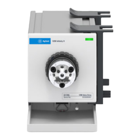
Page 122: Front And Rear View Of The Module
Hardware Information Electrical Connections Front and Rear View of the Module Status lamp Serial number label Figure 13 Front View of 1290 Infinity II Valve Drive 1290 Infinity II Valve Drive and Valve Heads User Manual... - Page 123 Hardware Information Electrical Connections Fuses External leak sensor connector Config switch CAN ports Power switch Power connector Figure 14 Rear View of 1290 Infinity II Valve Drive 1290 Infinity II Valve Drive and Valve Heads User Manual...
-
Page 124: Interfaces
Hardware Information Interfaces Interfaces The Agilent InfinityLab LC Series modules provide the following interfaces: Table 8 Agilent InfinityLab LC Series Interfaces Module RS-232 Analog APG (A) Special (on-board) / ERI (E) Pumps G7104A/C G7110B G7111A/B, G5654A G7112B G7120A, G7132A G7161A/B... - Page 125 Hardware Information Interfaces Table 8 Agilent InfinityLab LC Series Interfaces Module RS-232 Analog APG (A) Special (on-board) / ERI (E) Fraction Collectors G7158B G7159B G7166A Requires a host module with on-board LAN with minimum FW B.06.40 or C.06.40, or with...
-
Page 126: Overview Interfaces
Remote (ERI) The ERI (Enhanced Remote Interface) connector may be used in combination with other analytical instruments from Agilent Technologies if you want to use features as common shut down, prepare, and so on. It allows easy connection between single instruments or systems to ensure coordinated analysis with simple coupling requirements. - Page 127 Hardware Information Interfaces To provide maximum safety within a distributed analysis system, one line is dedicated to SHUT DOWN the system’s critical parts in case any module detects a serious problem. To detect whether all participating modules are switched on or properly powered, one line is defined to summarize the POWER ON state of all connected modules.
- Page 128 Hardware Information Interfaces Table 9 ERI signal distribution Signal Description START REQUEST (L) Request to start injection cycle (for example, by start key on any module). Receiver is the autosampler. STOP (L) Request to reach system ready state as soon as possible (for example, stop run, abort or finish and stop injection).
-
Page 129: Eri (Enhanced Remote Interface)
ERI replaces the AGP Remote Interface that is used in the HP 1090/1040/1050/1100 HPLC systems and Agilent 1100/1200/1200 Infinity HPLC modules. All new InfinityLab LC Series products using the FUSION core electronics use ERI. This interface is already used in the Agilent Universal... - Page 130 Hardware Information Interfaces Enhanced Remote IO 1 (START REQUEST) IO 2 (STOP) IO 3 (READY) IO 4 (POWER ON) IO 5 (NOT USED) IO 6 (SHUT DOWN) IO 7 (START) IO 8 (PREPARE) 1 wire DATA DGND +5 V ERI out PGND PGND +24 V ERI out...
-
Page 131: Usb (Universal Serial Bus)
Hardware Information Interfaces 5V Distribution (Future Use) • Available directly after turning on the hosting module (assures that the firmware can detect certain basic functionality of the device). • For digital circuits or similar. • Provides 500 mA maximum. • Short-circuit proof with automatic switch off (by firmware). -
Page 132: Config Switch Settings Of The Infinity Ii Valve Drive
Hardware Information Config Switch Settings of the Infinity II Valve Drive Config Switch Settings of the Infinity II Valve Drive Configuration Switch Settings Figure 16 Config Switches Table 10 Dip switches settings for G1170A Mode select Default right right Coldstart right left Boot resident... - Page 133 Hardware Information Config Switch Settings of the Infinity II Valve Drive Special Settings Boot-Resident Firmware update procedures may require this mode in case of firmware loading errors (main firmware part). If you use the following switch settings and power the instrument up again, the instrument firmware stays in the resident mode. It is not operable as a module.
-
Page 134: Appendix
In Case of Damage Solvents Symbols Waste Electrical and Electronic Equipment (WEEE) Directive Radio Interference Sound Emission Solvent Information Agilent Technologies on Internet This chapter provides additional information on safety, legal and web. 1290 Infinity II Valve Drive and Valve Heads User Manual... -
Page 135: General Safety Information
Appendix General Safety Information General Safety Information General Safety Information The following general safety precautions must be observed during all phases of operation, service, and repair of this instrument. Failure to comply with these precautions or with specific warnings elsewhere in this manual violates safety standards of design, manufacture, and intended use of the instrument. -
Page 136: Before Applying Power
Verify that the voltage range and frequency of your power distribution matches to the power specification of the individual instrument. Never use cables other than the ones supplied by Agilent Technologies to ensure proper functionality and compliance with safety or EMC regulations. -
Page 137: Do Not Operate In An Explosive Atmosphere
Appendix General Safety Information Do Not Operate in an Explosive Atmosphere Presence of flammable gases or fumes WAR N IN G Explosion hazard Do not operate the instrument in the presence of flammable gases or fumes. Do Not Remove the Instrument Cover Instrument covers removed WAR N IN G Electrical shock... -
Page 138: Solvents
Appendix General Safety Information Solvents Toxic, flammable and hazardous solvents, samples and reagents WAR N IN G The handling of solvents, samples and reagents can hold health and safety risks. When working with these substances observe appropriate safety procedures (for example by wearing goggles, safety gloves and protective clothing) as described in the material handling and safety data sheet supplied by the vendor, and follow good laboratory practice. -
Page 139: Symbols
Appendix General Safety Information Symbols Table 11 Symbols The apparatus is marked with this symbol when the user shall refer to the instruction manual in order to protect risk of harm to the operator and to protect the apparatus against damage. Indicates dangerous voltages. - Page 140 Appendix General Safety Information Table 11 Symbols Magnetic field Magnets produce a far-reaching, strong magnetic field. They could damage TVs and laptops, computer hard drives, credit and ATM cards, data storage media, mechanical watches, hearing aids and speakers. Keep magnets at least 25 mm away from devices and objects that could be damaged by strong magnetic fields.
-
Page 141: Waste Electrical And Electronic Equipment (Weee) Directive
Appendix Waste Electrical and Electronic Equipment (WEEE) Directive Waste Electrical and Electronic Equipment (WEEE) Directive This product complies with the European WEEE Directive marking requirements. The affixed label indicates that you must not discard this electrical/electronic product in domestic household waste. Do not dispose of in domestic household waste NOTE To return unwanted products, contact your local Agilent office, or see... -
Page 142: Radio Interference
Appendix Radio Interference Radio Interference Never use cables other than the ones supplied by Agilent Technologies to ensure proper functionality and compliance with safety or EMC regulations. Test and Measurement If test and measurement equipment is operated with equipment unscreened... -
Page 143: Sound Emission
Appendix Sound Emission Sound Emission Sound pressure Sound pressure Lp <70 db(A) according to DIN EN ISO 7779 Schalldruckpegel Schalldruckpegel Lp <70 db(A) nach DIN EN ISO 7779 1290 Infinity II Valve Drive and Valve Heads User Manual... -
Page 144: Solvent Information
Appendix Solvent Information Solvent Information Observe the following recommendations on the use of solvents. • Brown glass ware can avoid growth of algae. • Avoid the use of the following steel-corrosive solvents: • solutions of alkali halides and their respective acids (for example, lithium iodide, potassium chloride, and so on), •... -
Page 145: Agilent Technologies On Internet
Appendix Agilent Technologies on Internet Agilent Technologies on Internet For the latest information on products and services visit our worldwide web site on the Internet at: http://www.agilent.com 1290 Infinity II Valve Drive and Valve Heads User Manual... - Page 146 In This Book This User’s Guide describes common applications as well as installation, operation and maintenance of the Agilent InfinityLab LC Series 1290 Infinity II Valve Drive (G1170A) and Agilent InfinityLab Quick Change Valves. www.agilent.com Agilent Technologies Inc. 2011-2021 Edition: 06/2021 Document No: SD-29000412 Rev.