Advertisement
Quick Links
The BMPlus Zone Control System allows you to easily
upgrade an inefficient single zone HVAC system, into a
Multi-zone, Energy savings, Comfort producing, HVAC
system. The Superior Design, Intuitive Firmware, Simple
Setup Options, Easy to Understand wiring and Backwards
Compatibility, makes the BMPlus Zoning system the
Contractors dream. Combined with EWC Motorized
Dampers and Any off-the-shelf Thermostats, EWC Controls
sets a another high standard in the residential & light
commercial Forced Air Zoning Industry.
The main module controls three zones
Zone
using motorized dampers and may be
Capacity
expanded up to 5, or 7 zones, using 1 or
2 XM2 Expansion Modules.
Compatible
Controls 2 stage conventional or dual fuel
heat pumps, without the need for dual fuel
HVAC
kits. Also single or two-stage gas, oil, &
Systems
hydronic heating systems, with single or
two stage air conditioning. Constant or
variable speed fan systems.
Not compatible with 2 speed / 2 stage compressor heat pumps.
(3 stage heat pumps).
Compatible with any off the shelf
Compatible
H e a t
Thermostats
(2heat/1cool). You may also use
any regular Heat/Cool thermostat
(1heat/1cool). You may still use
regular Heat/Cool thermostats to
control a Heat Pump system.
Automatic
The BMPlus Zone system features
automatic changeover from any
Heat/Cool
thermostat allowing for individual zone
Changeover
comfort from the HVAC system.
Status LED
The STATUS LED pulses as a steady
heart beat to indicate active Micro-
processor status.
On board LED's illuminate to indicate
System LEDs
HVAC system mode, system status,
active and inactive zone identification.
See page 10 for details.
Damper LEDs
LEDs labeled Zone 1 thru Zone 7 indicate
which dampers are energized open.
All modules operate on 24vac power
Operating
supplied from a separate transformer. A
Power
single 40va transformer can power up to 7
zones with a total of 7 ND/URD dampers
directly connected. See page 9 for
details.
TB-228
EWC Controls Inc. 385 Highway 33 Englishtown, NJ 07726 800-446-3110 FAX 732-446-5362
P/N 090375A0228 9 November 2007 REV. B
P u m p
T h e r m o s t a t
©
Copyright
2007 EWC Controls All Rights Reserved
Models BMPlus 3000/5000/7000 Rev. B
Leave this bulletin on the job site for future reference!
J 1
43
21
40
46
14
28
ZONE3
37
49
7
35
MOTOR
M6
42
34
52
OFF
2
ND
STAGE
LOW TEMP
M4
TIMER
OAS
LIMIT
R 1
R
2
C
5
M2
R
K
1
M1
R
ZONE2
D
1
MOTOR
U
1
K
2
M6
M4
M2
2
D
M1
K
3
C
ZONE1
9
U
MOTOR
3
D
M6
D 4
F1
M4
+
+
M2
M1
C 1
C 2
SW 3
4
K
24
VAC
T'FORMER
OAS
R
OFF
D
5
R 19
C
5
K
R 20
SYSTEM
21
R
G
D
6
R
22
Y2
6
K
23
R
Y1
R 24
O
R
25
R
26
D
7
W1 B
R
27
K
7
W2 E
R 28
RH
R
29
RC
30
R
D
8
C
R
31
K
8
R
32
RC
RH
LINK
33
R
R
34
E W C
D 9
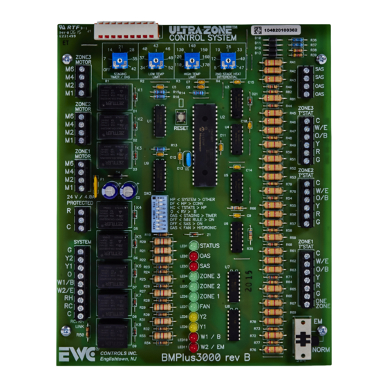
Figure 1
* BMPlus 3000 Control Panel
Contents
* Supply Air Sensor
* Technical Bulletin TB228
* Mounting Hardware
Thermal
The BMPlus module has a Thermal
Circuit
circuit breaker that protects the
Breaker
module(s) from shorts in the damper
and thermostat field wiring. It will
not protect against shorts in the
HVAC system wiring.
CAUTION:
is tripped it will get quite hot. To
reset the breaker: Shut off power to
the panel. Find and repair the short.
Restore the 24VAC power.
Indoor Fan
Any zone can activate the indoor fan
and only the dampers in zones calling
Control
for continuous fan operation will open.
Continuous fan operation will only
occur when there are no active or
pending, heat or cool demands. A dip
switch is provided to enable automatic
fan operation in heat mode. Useful for
straight electric heat or hydronic heat
applications. Fan operation is
s e a m l e s s a n d o c c u r s w i t h o u t
interruption from Cool to Heat mode.
CONTROL
SYSTEM
D 10
140
26
D 11
130
150
19
33
D 12
120
160
D 13
12
40
110
170
5
47
HIGH TEMP
2
ND STAGE HEAT
LIMIT
DIFFERENTIAL
R
3
R
4
C
7
C
15
C
8
15
U
3
R 40
16
D
21
R 14
R
82
R 44
U
2
C 10
RESET
4
U
C 11
R
48
R 13
12
R
50
13
C
C
14
Y 1
U
5
R
<
>
HP
SYSTEM
GAS
R
54
DF
<
HP
>
CONV
<
>
HC
TSTATS
HP
O
<
RV
>
B
R
66
<
>
2
ND
STAGE
TIMER
C
9
OFF
<
50
%
RULE
>
ON
<
>
SAS
ON
U
6
GAS
<
FAN
>
HYDRONIC
R
58
Z
1
STATUS
R
60
LED
1
R 35
OAS
LED
2
SAS
3
LED
U
7
ZONE
3
LED
4
R
71
R 64
ZONE
2
LED
5
ZONE
1
R
68
LED
6
LED
7
FAN
U
8
2
Y
LED
8
R 70
1
Y
LED
9
R
73
W
1
B
72
R
LED
10
R
77
W
2
EM
LED
11
R 76
BMPlus3000B
When the circuit breaker
E-Mail- info@ewccontrols.com
R
36
R
37
R
38
R
39
R
41
SAS
R 42
SAS
43
R
OAS
OAS
R
81
ZONE3
R
45
T
STAT
C
R
46
W/E
R 47
O/B
R
49
Y
R
R 51
G
R
52
ZONE3
ZONE3
R
53
T T
STAT
STAT
79
C
R 78
W/E
O/B
R
55
Y
R
56
R
R 57
G
R
59
ZONE1
T
STAT
R 61
C
W/E
R
62
O/B
R 63
Y
R
R
65
G
ONE
R
67
ZONE
R
69
EM
NORM
SW 4
1
Advertisement

Related Manuals for EWC Controls BMPlus 3000


Summary of Contents for EWC Controls BMPlus 3000
- Page 1 TB-228 interruption from Cool to Heat mode. EWC Controls Inc. 385 Highway 33 Englishtown, NJ 07726 800-446-3110 FAX 732-446-5362 E-Mail- info@ewccontrols.com © P/N 090375A0228 9 November 2007 REV. B...
- Page 2 The last Damper(s) will be held Open for 90 seconds at the end of every call Timer Heat Pump thermostats. allowing a system purge into the last zone that was calling. EWC Controls Inc. 385 Highway 33 Englishtown, NJ 07726 800-446-3110 FAX 732-446-5362 E-Mail- info@ewccontrols.com...
- Page 3 Remember that you can use standard HC T-stats on a Heat Pump application. IMPORTANT NOTE: The BMPlus 3000 Zone Control System allows Heat Pump thermostats to be connected to all zones. When doing so, make sure you turn the 2nd stage timer to the “OFF” position. Using heat pump thermostats means that the zone panel will obey thermostatic demands and ignore Timer operations.
-
Page 4: Installation & Wiring Instructions
W2 timer. Also, Emergency heat can be T’STAT activated from any zone. NOTE: The New BMPlus 3000 allows the user to install Heat Pump thermostats on all zones. This allows the user to turn off the W2 Timer and energize the auxiliary heat via... - Page 5 Unoccupied..When the building is Occupied, the thermostat will de-energize (open contact) the One Zone Terminal. EWC Controls Inc. 385 Highway 33 Englishtown, NJ 07726 800-446-3110 FAX 732-446-5362 E-Mail- info@ewccontrols.com...
-
Page 6: System Wiring
Timer OFF. When the thermostat 2nd stage heat demand is satisfied, controlled via the time delay relay inside the air handler. the BMPlus 3000 will stage down, unless DF or OAS has been selected and the outdoor temperature is lower than the OAS changeover setting. In that Don’t worry if you accidentally cut the Rc/Rh link. - Page 7 *1 ZONE MODE COMPLIES WITH CALIFORNIA TITLE 24 * HIGHEST LEVEL OF THERMOSTAT COMPATABILITY * ADJUSTABLE DIFFERENTIAL LIMIT CONTROL * SIMPLIFIED WIRING AND EASY SYSTEM SETUP EWC Controls Inc. 385 Highway 33 Englishtown, NJ 07726 800-446-3110 FAX 732-446-5362 E-Mail- info@ewccontrols.com...
- Page 8 A Spring Close Damper is wired to M1 & M4 Figure 15 Have a Multi-Meter, pocket screw driver and wire snips on hand. EWC Controls Inc. 385 Highway 33 Englishtown, NJ 07726 800-446-3110 FAX 732-446-5362 E-Mail- info@ewccontrols.com...
- Page 9 SR / ESR / RSD Power Open / Spring Close Dampers - Connect 24vac common & hot to the two motor (M) terminals. Damper should Open. Remove 24vac hot. Damper should Close. EWC Controls Inc. 385 Highway 33 Englishtown, NJ 07726 800-446-3110 FAX 732-446-5362 E-Mail- info@ewccontrols.com...
- Page 10 The W2/E LED illuminates solid to indicate 2nd stage of HEATING is energized in GAS/HYDRONIC W2/E or HEAT PUMP mode. The W2/E LED illuminates solid to indicate EMERGENCY HEAT is energized in HEAT PUMP mode. NOTES: EWC Controls Inc. 385 Highway 33 Englishtown, NJ 07726 800-446-3110 FAX 732-446-5362 E-Mail- info@ewccontrols.com...
- Page 11 On-Board Emergency Switch The BMPlus 3000 Zone Control System includes Module to Module Factory Wiring. We power up the Expansion Modules for you. The XM2 Expansion module includes a Status LED and Damper Status LED’s. See page 11 and 12 for drawing representations of a 5 and 7 zone system and appropriate dip switch settings.
- Page 12 ZONE R 64 ZONE W1 B ZONE W2 E R 28 ZONE R 70 LINK E W C NORM R 76 BMPlus3000B SW 4 Figure 20 EWC Controls Inc. 385 Highway 33 Englishtown, NJ 07726 800-446-3110 FAX 732-446-5362 E-Mail- info@ewccontrols.com...
- Page 13 R 64 ZONE W1 B ZONE W2 E R 28 ZONE R 70 LINK E W C NORM R 76 BMPlus 3000 rev.B SW 4 Figure 21 EWC Controls Inc. 385 Highway 33 Englishtown, NJ 07726 800-446-3110 FAX 732-446-5362 E-Mail- info@ewccontrols.com...
-
Page 16: Troubleshooting
BMPlus 3000 for Heat Pump applications. TECHNICAL SUPPORT EWC Controls provides superior toll free Troubleshooting Support for the BMPlus 3000 when you are on the job site! Call 1-800-446-3110 Monday - Friday 8am to 5pm EST Otherwise call 1-732-446-3110 for information on the BMPlus 3000 and other ULTRA-ZONE products..
Need help?
Do you have a question about the BMPlus 3000 and is the answer not in the manual?
Questions and answers