Table of Contents
Advertisement
Advertisement
Table of Contents
Troubleshooting

Related Manuals for Epson EH-TW2900


Summary of Contents for Epson EH-TW2900
- Page 1 SERVICE MANUAL Multimedia Projector EH-TW2900/3500/4400/4500/5500 CONFIDENTIAL...
- Page 2 Other company or product names used herein are for identification purpose only and may be trademarks or registered trademarks of their respective owners. EPSON disclaims any and all rights in those marks.
- Page 3 EH-TW2900/3500/4400/4500/5500 CONFIDENTIAL About This Manual This manual describes basic functions, theory of electrical and mechanical operations, maintenance and repair procedures of the product. The instructions and procedures included herein are intended for the experienced repair technicians, and attention should be given to the precautions on the preceding page.
- Page 4 EH-TW2900/3500/4400/4500/5500 CONFIDENTIAL IMPORTANT PRECAUTIONS IN SAFETY AND MAINTENANCE PERFORMANCE Here describes the important points to keep in mind in repair and maintenance performance. SYMBOLS To prevent injury to the repair technicians and to protect the devices, the categorized safety instructions are provided in this manual with the symbols below. Be sure to read and understand their meanings before proceeding to the next section.
- Page 5 EH-TW2900/3500/4400/4500/5500 CONFIDENTIAL SAFETY INSTRUCTIONS Never modify the product for any reason whatsoever. (Except for a case that is under the instructions to do so.) The precautionary measures itemized below should be fully understood when performing repair and maintenance procedures. Never peer through the projection lens during repair/maintenance work when the power is on.
- Page 6 EH-TW2900/3500/4400/4500/5500 CONFIDENTIAL Be careful not to drop a metal part such as a screw, a washer, or a clip into the inside of the product. If such cases should occur accidentally, never turn on the power supply until all the dropped parts are found and removed.
- Page 7 EH-TW2900/3500/4400/4500/5500 CONFIDENTIAL REVISION HISTORY After first release of this manual, the parts and mechanism may be subject to change for improvement of their performance and the manual may be revised. Be sure to always keep this manual up to date.
-
Page 8: Table Of Contents
4.1.1 How To Display the AS (After Service) Menu ......... 102 3.3.1 Air Filter Assembly ..................54 4.1.2 Displaying the Pages ................. 102 3.3.2 Lamp ......................55 4.1.3 Initializing (Resetting) the AS Menu Values ..........106 SEIKO EPSON Revision A... -
Page 9: Chapter 1 Product Description
C H A P T E R PRODUCT DESCRIPTION CONFIDENTIAL... -
Page 10: About Model Names
In this chapter, the models are categorized into two group according to the mechanical differences, and named generally as shown below. Destination ASIA Notation PowerLite Pro Cinema 9500UB EH-TW5500 EH-TW5500 EH-TW4500/5500 PowerLite Home Cinema 8500UB EH-TW4500 EH-TW4400 PowerLite Pro Cinema 9100 EH-TW3500 PowerLite Home Cinema 8100 EH-TW3500 EH-TW3500 EH-TW2900 SEIKO EPSON Revision A... -
Page 11: Features
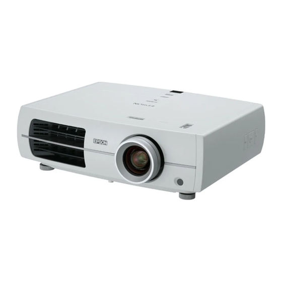
Figure 1-1. External View • Security slot HDMI terminals Direct Power On Size Dimensions 360 mm (D) x 450 mm (W) x 136 mm (H) (With feet retracted) Weight: 7.3 Kg/ 16.1lbs (EH-TW3500) 7.5 kg/ 16.5lbs (EH-TW4500/5500) SEIKO EPSON Revision A... -
Page 12: Specifications
Normal 0 m to 2286 m <0 ft to 7500 ft> Start-up period Approx. 17 seconds Approx. 19 seconds Cool-down period Approx. 16 seconds ± Power supply voltage 100 - 240 V AC 10%, 50/60 Hz SEIKO EPSON Revision A... - Page 13 360 (D) x 450 (W) x 145 (H) Weight Approx. 16.1 lbs/ 7.3 kg Approx. 16.5 lbs/ 7.5 kg High Brightness mode 30 dB 30 dB (TBD) Fan noise Low Brightness mode 22 dB 22 dB (TBD) SEIKO EPSON Revision A...
-
Page 14: External Dimensions
EH-TW3500/4500/5500 Product Description CONFIDENTIAL 1.4 External Dimensions 29.7 359.9 29.9 56.9 129.8 12.7 37.9 148.7 Unit: mm 65.9 SEIKO EPSON Revision A... - Page 15 EH-TW3500/4500/5500 Product Description CONFIDENTIAL 14.2 1.18 2.24 5.11 5.08 1.49 Unit: inch SEIKO EPSON Revision A...
-
Page 16: Chapter 2 Troubleshooting
C H A P T E R TROUBLESHOOTING CONFIDENTIAL... -
Page 17: Required Tools
To secure parts repair or cleaning. General tools 1set Tools given in "3.1.5 Tools (p49)" Reassembly, operation check and Safety check* *In the case that a safety device (p.96) is repaired or maintained. Finish Figure 2-1. Troubleshooting Workflow SEIKO EPSON Revision A... -
Page 18: Exterior Check
Any damage/deformation/cracking due to external forces? Lower Case Any foreign object/dirt on the filter cover or the vents? Any foreign object/dirt on IR receivers? Does Front Foot work smoothly to adjust height? Foot Any Foot Rubber detached? SEIKO EPSON Revision A... -
Page 19: Problem Diagnosis And Troubleshooting
Switch. The lamp turns off automatically, and the projection stops. Left the projector for 5 minutes untouched, it switches to the High Temp Error standby mode. (overheating) [Status] The internal temperature rises over the specified level. SEIKO EPSON Revision A... - Page 20 • If the air filter is clogged, clean or replace it. Error Orange Abnormality is detected from the elements on a circuit board. Orange Sub System Warning to Communication Error Replace the lamp with a new one. replace Lamp Orange SEIKO EPSON Revision A...
-
Page 21: Troubleshooting Based On Led Indications
Error Code on Electric Circuit on the AS Menu, then carry out the remedy referring to the reference on the right Errors (p31)" column. RS: Sub system ROM Error Orange Internal Error (4) RP: Sub System Communication Error ê‘ SEIKO EPSON Revision A... - Page 22 " Troubleshooting from the CF: Cinema Filter Error and check the error code on the AS Menu, then carry out the remedy referring to Error Code on Electric the reference on the right column. Circuit Errors (p31)" SEIKO EPSON Revision A...
- Page 23 • Air Filter's condition (dirt accumulation, clogging) LF: Lamp failure When clogging or the like is found, clean or replace the filter. • When using the projector at an altitude of 1500 m or more, set “High Altitude Mode” to “On” SEIKO EPSON Revision A...
-
Page 24: Troubleshooting From The Error Code
START Check the Error Code from AS menu. Locate the defective parts referring to the table below with the Error Code. Repair/replace the defective parts. Figure 2-3. Flowchart of Troubleshooting SEIKO EPSON Revision A... - Page 25 Replace the PS Ballast. "3.3.15 PS Ballast (p92)" Safety Switch on the AC Cable is Safety Switch (AC Cable) Replace the AC Cable. "3.3.17 AC Cable (p94)" broken. Lamp PS Ballast Air Filter Lamp Burnt Out Error Safety Switch SEIKO EPSON Revision A...
- Page 26 PS Ballast is broken. Replace the PS Ballast. "3.3.15 PS Ballast (p92)" Safety Switch on the AC Cable is Safety Switch (AC Cable) Replace the AC Cable. "3.3.17 AC Cable (p94)" broken. PS Ballast Lamp Lamp Failure Safety Switch SEIKO EPSON Revision A...
- Page 27 "3.3.16 Removing the Lower Replace the parts with deformed vent. Case (p93)" TH Board (2) EX Fan (assembly) TH Board (PS Ballast) Vent Cable TH Internal Overheat error Light Valve TH Air Filter Cable C170 Vent TH Board (1) SEIKO EPSON Revision A...
- Page 28 • "3.3.7.2 PS Fan (p67)" PS Fan abnormal. • "3.3.10 Lamp Fan (p83)" Accumulation of dust occurs on a fan. Clean the fan of accumulated dust. PS Fan Lamp Fan EX Fan INT Fans Fan error SEIKO EPSON Revision A...
- Page 29 Elements for temperature control on (assembly) (p68)" MA Board above, replace the Optical Engine and MAB set MA Board are broken. • "3.3.9 Removing the Optical because they are broken. Engine (assembly) (p75)" MA Board Fan error Optical Engine SEIKO EPSON Revision A...
- Page 30 "3.3.9 Removing the Optical because they are broken. Engine (assembly) (p75)" TH Board (2) PS Ballast MA Board Cable TH TH Board (PS Ballast) Thermistor error Light Valve TH Cable C170 TH Board (1) Optical Engine SEIKO EPSON Revision A...
- Page 31 MA Board is broken. Sub system PW Error Replace the Optical Engine and MAB set. Sub System (Electric Circuit Sub System becomes abnormal. Sub system ROM Error other than MA Board) Replace MA Board. MA Board Optical Engine SEIKO EPSON Revision A...
- Page 32 EH-TW3500/4500/5500 Troubleshooting CONFIDENTIAL Error code/error name Faulty part/part name Cause Remedy Reference Auto Iris Auto Iris is broken. Replace the Auto Iris. "3.3.9.2 Auto Iris (p79)" Auto Iris Error Auto Iris SEIKO EPSON Revision A...
- Page 33 Replace the CF Frame. CF Switch CF Switch is broken. Replace the CF Switch. CF Motor CF Motor is broken. Replace the CF Motor. "3.3.9.4 CF Motor (p82)" CF Switch Cinema Filter Error CF Motor CF Frame SEIKO EPSON Revision A...
-
Page 34: Troubleshooting Without Error Indications
LC Switch (AC Cable) LC switch is broken. Replace the LC Switch with a new one. "3.3.17 AC Cable (p94)" LC Switch PS Ballast Lamp Cover SW1 Board The projector does not operate at SW1 Cable all. SEIKO EPSON Revision A... - Page 35 Replace the Optical Engine and MAB set. Engine (assembly) (p75)" "3.3.9.1 Focus Ring/Zoom Ring Zooming cannot be made. Zoom Ring Zoom Ring is broken. Replace the Zoom Ring. (p78)" Zoom Ring Optical Engine MA Board Focus Ring Optical Engine Projection Lens SEIKO EPSON Revision A...
- Page 36 Black part of image is yellowish. FPC for L/V (B) is not connected Connect the FPC of L/V (B) to the DR Board correctly. (EH-TW4500/5500) properly. MA Board DR Board (EH-TW4500/5500 only) Optical Engine Optical Engine SEIKO EPSON Revision A...
- Page 37 MA Board replace the Optical Engine and MAB set because they are Board are broken. • "3.3.9 Removing the Optical broken. Engine (assembly) (p75)" RC Cable RCR Board MA Board RC Cable RCF Board Optical Engine SEIKO EPSON Revision A...
- Page 38 Elements for operation control on MA (assembly) (p68)" MA Board replace the Optical Engine and MAB set because they are Board are broken. • "3.3.9 Removing the Optical broken. Engine (assembly) (p75)" SW1 Board MA Board SW2 Board Optical Engine SEIKO EPSON Revision A...
- Page 39 Cables Burn on cables from heat. If burn on cables occurs, replace them with new ones. PS Ballast Burn on a circuit board from heat. Replace the PS Ballast. "3.3.15 PS Ballast (p92)" Lamp PS Ballast SEIKO EPSON Revision A...
- Page 40 Lamp Fan • "3.3.7.2 PS Fan (p67)" PS Fan Fan’s impeller is broken. Replace the broken fan with a new one. • "3.3.10 Lamp Fan (p83)" PS Fan PS Ballast Lamp Fan EX Fan INT Fans SEIKO EPSON Revision A...
-
Page 41: Cable Connection And Projector's Status
CN1306 CN1902 CN1904 CN1308 CN1501 CN1305 DR Board CN1302 CN1505 CN1503 CN3800 CN4200 Figure 2-4. Connector layout of the MA Board (EH-TW3500) CN4000 CN5001 CN5000 Figure 2-5. Connector layout of the MA Board/ DR Board (EH-TW4500/5500) SEIKO EPSON Revision A... - Page 42 (See " Troubleshooting from the Error (See " Trouble Shooting on Lamp Errors (p23)".) Code on Electric Circuit Errors (p31)".) SEIKO EPSON Revision A...
- Page 43 Auto Iris Sensor automatically after a certain period. The LED (DR Board) Indicator’s warning display can be turned off once the main power is turned off. (See " Troubleshooting from the Error Code on Electric Circuit Errors (p31)".) SEIKO EPSON Revision A...
-
Page 44: Operation And Safety Check After Repair
Does [Power] button on the controller switch on/off the projector? 1. Press [Power] button on Remote Do all the buttons function correctly? Controller to turn the projector on. Can Remote Controller work approx. 6m away from the front/rear of the projector? SEIKO EPSON Revision A... - Page 45 7. Adjust keystone with the [Keystone] buttons of the controller. 8. From menu, select [Position], and adjust it. 9. Connect all the IF cables to check. Is image vivid enough? 10.Press [Source] button, and switch to the corresponding source. SEIKO EPSON Revision A...
-
Page 46: Chapter 3 Disassembly And Assembly
C H A P T E R DISASSEMBLY AND ASSEMBLY CONFIDENTIAL... -
Page 47: Precautions
The Optical Engine is very sensitive to vibration and shocks, so handle it with care. The speaker unit contains a permanent magnet, so keep it away from any storage media such as floppy disks and magnetic cards. SEIKO EPSON Revision A... -
Page 48: Precautions
Disconnect any interface cables from the projector. the safety checks. Before disassembling the projector, make sure to clean any dust or dirt on the air filter, interface section and outer case using a vacuum cleaner or other method. Finish SEIKO EPSON Revision A... -
Page 49: Standard Operation Time
Use commercially available Polyimide Heat-resistant tape q.s.* tape generally called “KAPTON® TAPE”. Brush Cleaning away dust Vacuum cleaner Cleaning away dust Lens cleaner q.s.* Cleaning the projection lens Gloves Anti-static wrist band Note : q.s.: Sufficient quantity SEIKO EPSON Revision A... -
Page 50: Precautions For Optical Engine And Ma Board
Do not disassemble the Optical Engine. Special jigs are required for reinstalling the optical components in the engine, such as POP Assy., condenser lens, mirrors. Reassembling the Optical Engine without using the jigs are strictly prohibited. SEIKO EPSON Revision A... -
Page 51: Flowchart
“ 3.3.8 Removing the MA Board removed to reach the parts in yellow. (assembly) (p68)” “ 3.3.8.3 DR Board (EH-TW4500/ 5500 series only) (p73)” “ 3.3.9 Removing the Optical Engine (assembly) (p75)” “ 3.3.9.1 Focus Ring/Zoom Ring (p78)” SEIKO EPSON Revision A... - Page 52 “ 3.3.13 Inner EX Duct (p90)” “ 3.3.13 Inner EX Duct (p90)” “ 3.3.15 PS Ballast (p92)” “ 3.3.14 TH Board (2) (p91)” “ 3.3.15 PS Ballast (p92)” “ 3.3.11 INT Fan (assembly) (p85)” “ 3.3.16 Removing the Lower Case (p93)” SEIKO EPSON Revision A...
- Page 53 “ 3.3.7.1 EX Fan (p66)” “ 3.3.8.3 DR Board (EH-TW4500/ “ 3.3.10 Lamp Fan (p83)” 5500 series only) (p73)” “ 3.1.6 Precautions for Optical Engine and MA Board (p50)” “ 3.3.11 INT Fan (assembly) (p85)” “ 3.3.11.1 INT Fan (p87)” SEIKO EPSON Revision A...
-
Page 54: Disassembly
3.3.1 Air Filter Assembly Standard Operation Time - Min. Release the two hooks and remove the Air Filter Cover. Remove the Air Filter Assembly. Air Filter Assembly Hooks Air Filter Cover Figure 3-1. SEIKO EPSON Revision A... -
Page 55: Lamp
Insert the a flat-blade screwdriver or similar tools into the holes of the IF Case on the location show in the figure below. Lamp Cover IF Case Hole Figure 3-3. Figure 3-2. SEIKO EPSON Revision A... -
Page 56: Front Foot
Remove the Foot Rubber from the Lower Case. the Foot Rubber. After attaching the Foot Rubber, make sure to press the part tightly to make it attached firmly. Front Foot Foot Rubber Foot Holder Lower Case Figure 3-4. SEIKO EPSON Revision A... -
Page 57: Side Case L/Side Case R
In the next step, make sure not to pull away the Side Case R too far because the cables are connected to it. Remove the three screws. Disconnect the SW2 Cable from the SW2 Board and remove the Side Case R from the Upper Case. Side Case R C.B.P-TITE SCREW,4X10,F/ZB-3C Figure 3-5. SEIKO EPSON Revision A... -
Page 58: Sw2 Board
Remove the four screws and remove the SW2 Board from the Side Button. Remove the Enter Button from the Side Case R. Remove the Side Button from the Side Case R. Side Button Enter Button Side Case R SW2 Board C.C.P-TITE SCREW,3X8,F/ZB-3C Figure 3-6. SEIKO EPSON Revision A... -
Page 59: Removing The Upper Case (Assembly)
Disconnect the SW1 Cable from the MA Board, and remove the Upper Case Remove the seven screws on the bottom (Lower Case side). (assembly). Upper Case (assembly) Lower Case SW1 Cable Upper Case (assembly) MA Board C.B.SCREW,3X6,F/ZB-3C C.B.P-TITE SCREW,4X10,F/ZB-3C Figure 3-8. Figure 3-7. SEIKO EPSON Revision A... - Page 60 Secure the Lamp Latch Cover with the screws. Upper Case (assembly) Backside Lamp Latch Cover Upper Case Latch Spring Spring holder (assembly) EX Seal Latch Spring Lamp Latch Cover Logo Plate Base C.C.P-TITE SCREW,3X8,F/ZB-3C Figure 3-9. SEIKO EPSON Revision A...
- Page 61 When replacing parts with caution labels attached, make sure to stick the label to the replaced parts. WARNING LABEL, LAMP WARNING LABEL, LOOK REPLACEMENT; LP49 INTO THE LENS CAUTION LABEL, HOT SEIKO EPSON Revision A...
-
Page 62: Sw1 Board
Remove the following parts from the Upper Case. • Top Button Diffusion Plate • LED Lens Upper Case Cushion LED Remove the following parts from the Top Button. • Diffusion Plate Top Button • Cushion LED LED Lens C.C.P-TITE SCREW,3X8,F/ZB-3C Figure 3-10. SEIKO EPSON Revision A... -
Page 63: Rcf Board/Rcr Board
Remove the screw and remove the RCR Board from the MA Plate. Remove the RCR Cable from the RCR Board. RCF Board RCR Cable MA Board RCR Board MA Board MA Plate Lower Case C.B.P-TITE SCREW,3X10,F/ZB-3C Figure 3-12. C.C.P-TITE SCREW,3X8,F/ZN-3C Figure 3-11. SEIKO EPSON Revision A... - Page 64 RCF Cable RCF Board Groove When installing the Decoration Plate R, make sure to align the positioning holes (x2) with the guide pins (x2) on the Lower Case. Positioning holes and guide pins Decoration Plate R SEIKO EPSON Revision A...
-
Page 65: Removing The Ex Fan (Assembly)
EX Fan (assembly). Disconnect the EX Fan Cable from the connector on the MA Board. Remove the four screws and remove the EX Fan (assembly). Power Unit Cable MA Board C.B.P-TITE SCREW,3X10,F/ZB-3C Figure 3-13. SEIKO EPSON Revision A... -
Page 66: Ex Fan
Remove the EX Duct PS from the EX Fan (assembly). Upper EX Duct EX Duct PS EX Fan Cushion EX Fan (assembly) EX Fan Decoration Plate L EX Fan Cushion Hooks Figure 3-14. Lower EX Duct C.B.P-TITE SCREW,3X10,F/ZB-3C Figure 3-15. SEIKO EPSON Revision A... -
Page 67: Ps Fan
Remove the eight LV Cushions from the PS Fan. The Sheet, Intake Fan is affixed to the PS Fan. LV Cushion Be sure to replace / affix the Sheet, Intake Fan, when replacing the PS Fan. PS Fan C.B.P-TITE SCREW,3X10,F/ZB-3C C.P.(S-P1)SCREW,3X5,F/ZN-3C Figure 3-16. SEIKO EPSON Revision A... -
Page 68: Removing The Ma Board (Assembly)
L/V (B) of Optical Engine CN1504 CN1303 CN1301 CN1701 CN1503 SW1 Board CN4000 Power Assembly CN1700 CN1504 RCF Board CN4000 CN2200 CN1300 CN2700 CN1304 CN2500 CN1703 CN1702 CN1507 CN1306 CN1308 CN1501 CN1305 CN1302 MA Board (assembly) CN1505 CN1503 Figure 3-17. SEIKO EPSON Revision A... - Page 69 CN1709 PS Fan CN1704 CF Switch CN1702 TH Board (PS Ballast) CN2100 Power Assembly CN1902 CN1904 MA Board (assembly) CN1710 TH Board (1) Figure 3-18. Note* : CN1302 is located on the back of the board. SEIKO EPSON Revision A...
- Page 70 10. Remove the eight screws and remove the MA Board (assembly). MA Board (assembly) MA Board (assembly) PS Plate PS Fan Duct PS Fan Duct PS Plate C.C SCREW,3X6,F/ZN-3C C.C SCREW,3X6,F/ZN-3C C.B.P-TITE SCREW,3X10,F/ZB-3C C.B.P-TITE SCREW,3X10,F/ZB-3C C.P.(O) SCREW,4X6,F/ZI C.P.(O) SCREW,4X6,F/ZI C.P.(S-P1)SCREW,3X5,F/ZN-3C C.P.(S-P1)SCREW,3X5,F/ZN-3C Figure 3-20. Figure 3-19. SEIKO EPSON Revision A...
-
Page 71: If Case
Remove the MA Board (assembly). (p.68) Remove the four screws, and remove the IF Case. Peel off the IF Label. Peel off the IF Shading Sheet. IF Shading Sheet IF Case IF Label C.B.SCREW,3X6,F/ZB-3C C.C.P-TITE SCREW,3X8,F/ZN-3C Figure 3-21. SEIKO EPSON Revision A... -
Page 72: Ma Board
Remove the 11 screws and remove the MA Board from the MA Plate. Remove the Gasket (1) from the MA Board. Remove the Gasket (2) from the MA Board (EH-TW4500/5500 series only). MA Plate C.C.SCREW,3X6,F/ZN-3C C.B.SCREW,3X6,F/ZB-3C C.B.P-TITE SCREW,3X10,F/ZB-3C 1/4-40X1/4,H.H.,F/NI,O SCREW Figure 3-22. SEIKO EPSON Revision A... -
Page 73: Dr Board (Eh-Tw4500/5500 Series Only)
Auto Iris Motor Remove the MA Board. (p.72) CN4000 L/V (G) of Optical Engine CN5001 Auto Iris Sensor Disconnect all the cables from the DR Board. CN3800 CN4200 CN3000 CN4000 CN5001 CN5000 DR Board Figure 3-23. SEIKO EPSON Revision A... - Page 74 Remove the screw and remove the Plate DR C from the DR Board. Plate DR B Plate DR A DR Board DR Board Plate DR C C.C SCREW,3X6,F/ZN-3C Figure 3-25. Plate DR A C.C SCREW,3X6,F/ZN-3C Figure 3-24. SEIKO EPSON Revision A...
-
Page 75: Removing The Optical Engine (Assembly)
Remove the screw that secures the GND cable (1) (EH-TW4500/5500 series only). Remove the four screws and remove the Optical Engine (assembly). Remove the screw and remove the Shade Sheet. Remove the Projection Lens Sheet from the Optical Engine (assembly). Screw to remove SEIKO EPSON Revision A... - Page 76 FOCUS RING;S Zoom Ring ZOOM RING Left MA Plate PLATE,MAFASTEN;LEFT Right MA Plate PLATE,MAFASTEN;RIGHT PRINTED CIRCUIT BOARD MA Board (assembly) ASSEMBLY;MA_R1 Shade Sheet EMI Sheet EMI, SUPPRESOR Gasket (1) GASKET 6_10_10 C.B.P-TITE SCREW,3X10,F/ZB-3C C.C SCREW,3X6,F/ZN-3C Figure 3-26. SEIKO EPSON Revision A...
- Page 77 SPRING,LG FASTEN Focus Ring FOCUS RING;S Zoom Ring ZOOM RING Left MA Plate PLATE,MAFASTEN;LEFT Right MA Plate PLATE,MAFASTEN;RIGHT PRINTED CIRCUIT BOARD DR Board (assembly) ASSEMBLY;DR_R1 Gasket (3) GASKET 2_3_35 Gasket (2) GASKET 13_10_40 EMI Sheet EMI, SUPPRESOR SEIKO EPSON Revision A...
-
Page 78: Focus Ring/Zoom Ring
Remove the Optical Engine (assembly). (p.75) Remove the three screws that secure the Zoom Ring. Remove the three screws and remove the Focus Ring. Remove the Zoom Ring. Zoom Ring Focus Ring C.P.B-TITE SCREW,1.7X4,F/NI Figure 3-27. SEIKO EPSON Revision A... -
Page 79: Auto Iris
TW4500/5500 series differs. Referring to the figures below, make sure to confirm the shape before installing the Auto Iris. A2 Shutter GND cable (2) EH-TW3500 series EH-TW4500/5500 series SCREW,AI FASTEN EH-TW4500/5500 series C.B.P-TITE SCREW,3X10,F/ZB-3C Figure 3-28. SEIKO EPSON Revision A... -
Page 80: Cf Frame
(EH-TW4500/5500 series only). (In EH-TW4500/5500 series’s case, remove the GND cable (2) screwed together.) CF Frame Remove the ML Fasten Spring from the CF Switch. Remove the CF Frame. Optical Engine (assembly) GND cable (2) EH-TW4500/5500 series C.B.P-TITE SCREW,3X10,F/ZB-3C Figure 3-29. SEIKO EPSON Revision A... - Page 81 When installing the CF Frame, make sure to align the center of the frame with the center of the CF Motor as shown below. Positions to hold CF Motor Edge of the frame CF Frame Center line SEIKO EPSON Revision A...
-
Page 82: Cf Motor
Remove the MA Board (assembly). (p.68) Remove the DR Board (EH-TW4500/5500 series only). (p.73) Remove the Optical Engine (assembly). (p.75) Remove the two screws and remove the CF Motor. Optical Engine (assembly) CF Motor C.B.P-TITE SCREW,3X10,F/ZB-3C Figure 3-30. SEIKO EPSON Revision A... -
Page 83: Lamp Fan
Remove the Lamp. (p.55) Remove the Side Cover L/Side Cover R. (p.57) Remove the Upper Case (assembly). (p.59) Remove the MA Board (assembly). (p.68) Remove the LC Switch from the Inner EX Duct. LC Switch Figure 3-31. SEIKO EPSON Revision A... - Page 84 The Sheet, Intake Fan is affixed to the Lamp Fan. Be sure to replace / affix the Sheet, Intake Fan, when replacing the Lamp Fan. Sheet, Intake Fan LV Cushion Lamp Fan C.B.P-TITE SCREW,3X10,F/ZB- Figure 3-32. SEIKO EPSON Revision A...
-
Page 85: Int Fan (Assembly)
Remove the Optical Engine (assembly). (p.75) Peel off the heat-resistant tape that secures the INT Fan cable to the MA-DR Plate. Remove the six screws, and remove the INT Fan (assembly). MA-DR Plate C.B.P-TITE SCREW,3X10,F/ZB-3C Figure 3-33. SEIKO EPSON Revision A... - Page 86 INT Duct. INT Fan cable Route the Cable C170 and the INT Fan cable through the guide on the Upper INT Duct. Cable C170 INT Fan cable Upper INT Duct Guide Hole Hole INT Seal C SEIKO EPSON Revision A...
-
Page 87: Int Fan
Remove the INT Seal B1 and INT Seal B2 from the INT Fan (assembly). Remove the three screws and Upper INT Duct from INT Fan. 10. Remove the INT Fan. Lower INT Duct INT Seal B2 C.B.P-TITE SCREW,3X10,F/ZB-3C Figure 3-34. SEIKO EPSON Revision A... - Page 88 When attaching the INT Seal B2 to the INT Fan (assembly), do not use the old one, but make sure to use a new one. INT Fan Light Valve Cushion INT Seal A INT Cushion Figure 3-35. SEIKO EPSON Revision A...
-
Page 89: Th Board (1)
Remove the DR Board (EH-TW4500/5500 series only). (p.73) Remove the Optical Engine (assembly). (p.75) Remove the INT Fan (assembly). (p.85) Remove the TH Board (1). Lower INT Duct Remove the Cable C170 from the TH Board (1). Figure 3-36. SEIKO EPSON Revision A... -
Page 90: Inner Ex Duct
11. Remove the Safety Switch from the Inner EX Duct. 12. Remove the screw ( ) and release Lamp Connector. 13. Remove the three screws and remove the Inner EX Duct. Safety Switch C.B.P-TITE SCREW,3X10,F/ZB-3C C.C.P-TITE SCREW,3X8,F/ZN-3C Figure 3-37. SEIKO EPSON Revision A... -
Page 91: Th Board (2)
Remove the PS Fan. (p.67) 10. Remove the Inner EX Duct. (p.90) 11. Remove the screw and remove the TH Board (2). 12. Remove the Cable TH from the TH Board (2). Cable TH C.C.P-TITE SCREW,3X8,F/ZN-3C Figure 3-38. SEIKO EPSON Revision A... -
Page 92: Ps Ballast
(p.67) 10. Remove the Inner EX Duct. (p.90) 11. Disconnect the AC Cable from the connector on the PS Board. 12. Remove the four screws and remove the PS Ballast. C.B.P-TITE SCREW,3x10,F/ZB-3C C.P.(O) SCREW,4x6,F/NI Figure 3-39. SEIKO EPSON Revision A... -
Page 93: Removing The Lower Case
16. Remove the EX Seal from the Lower Case. EX Seal Lower Case C.B.P-TITE SCREW,3X10,F/ZB-3C C.P.(O)SCREW,4X6,F/NI Figure 3-40. When attaching the Lower Shield to the Lower Case, do not use the old one, but make sure to use a new one. SEIKO EPSON Revision A... -
Page 94: Ac Cable
(p.67) Remove the Inner EX Duct. (p.90) When removing the AC Cable, take care not to damage the positioning pins (x4) on the Lower Case shown below. C.B.P-TITE SCREW,3X10,F/ZB-3C C.P.(O)SCREW,4X6,F/NI Figure 3-41. AC Cable Positioning pin SEIKO EPSON Revision A... - Page 95 Route the AC Cable under the shield plate. So as not to cross the AC Cable and the Lamp cable, route them in front and in the rear of the screw boss. Ferrite core Lamp cable AC Cable Shield plate Boss SEIKO EPSON Revision A...
-
Page 96: Safety Check After Servicing
• the processes that require the management to maintain the workers' safety. Safety Devices/Functions of this product • PS Ballast • Lamp • LC Switch • Caution Label, A Range selection • Caution Label, F switch SEIKO EPSON Revision A... - Page 97 7. Measure the insulation resistance between “a” and “c” (1) after one minute. 8. Measure the insulation resistance between “b” and “c” (2) in the same PC connector way as for (1). Exposed metal part of the device Figure 3-42. SEIKO EPSON Revision A...
- Page 98 Test conditions: Input a PC or video signal to the LCP and check the Should be no resistance (0.5Ω or less) illumination for about 5 minutes. • Judgment Projector should operate normally with no smoke or fire. SEIKO EPSON Revision A...
-
Page 99: Reference (Part Names Given In The Spi)
Lamp Fan Duct DUCT,LAMP FAN EX Fan FAN,EXHAUST Lamp Latch Cover LATCH,LID,LAMP EX Fan Cushion Cushion,Exhaust Fan Latch Spring SPRING,LATCH,LID LAMP EX Seal SEAL,EX LED Lens LENS,LED;PW Fan Holder HOLDER,FAN LG Spring SPRING,LG FASTEN Fan sheet SHEET,HOLDER,FAN. SEIKO EPSON Revision A... - Page 100 PS Fan FAN,PS PS Fan Duct DUCT,PS FAN PS Plate PLATE,GND,PS PRINTED CIRCUIT BOARD RCF Board ASSEMBLY;RCF_R1 RCF Cable CABLE,C;170 PRINTED CIRCUIT BOARD RCR Board ASSEMBLY;RCR_S2 RCR Cable CABLE RCR;FIF Shade Sheet SHEET,SHADE,LENS SHIFT Side Button BOTTON,SW;SIDE,B SEIKO EPSON Revision A...
-
Page 101: Chapter 4 Appendix
C H A P T E R APPENDIX CONFIDENTIAL... -
Page 102: As (After Service) Menu
The contents of each page are described next pages. The contents of this chapter are only for use of Epson Authorized Services. Do not disclose them to the end-users. This menu provides information and settings that are not displayed on the standard menu.You can check detailed information on the projector with it. - Page 103 : 0Times (12) (13) Destination Destination : XXXX : XXXX (14) Engine Type Engine Type : XXXXXX : XXXXXX P 0Z00023041XV111 P 0Z00023041XV111 (15) R R ------------ ------------ O O ------------ ------------ (16) J J 0Z1XV100 0Z1XV100 SEIKO EPSON Revision A...
- Page 104 Cool Down Completed : 0Time : 0Times Destinatio Destination : XXXXXXX : XXXXXXXX (10) Engine Typ Engine Type : XXXXX : XXXXXX (11) P 0Z00023041XV11 P 0Z00023041XV111 R R ----------- ------------ O ----------- ------------ J 0Z1XV10 0Z1XV100 (12) SEIKO EPSON Revision A...
- Page 105 ON was 0 hours 0 minutes 1 second, the projector’s status Error log items. see Table 4-1 “Error log items” was “Warming up”. Last 5 error logs are displayed. #2 (top) is the latest. Error count Control Data 1 Control Data 2 SEIKO EPSON Revision A...
-
Page 106: Initializing (Resetting) The As Menu Values
Error Count Reset to 0 Control data Thermal data of each ther- Acquired data of TEMP? of the Control mistor ESC/VP21 command Control Control data Acquired data of TEMP? of the Voltage of each fan ESC/VP21 command SEIKO EPSON Revision A... - Page 107 EH-TW3500/4500/5500 Appendix CONFIDENTIAL Top control panel Side control panel [Up] button [Right] button Source button [Enter] button [Down] button SEIKO EPSON Revision A...
Need help?
Do you have a question about the EH-TW2900 and is the answer not in the manual?
Questions and answers