Table of Contents

Related Manuals for MONARCH INSTRUMENT Phaser-Strobe pbx


Summary of Contents for MONARCH INSTRUMENT Phaser-Strobe pbx
- Page 1 Instruction Manual Phaser-Strobe pbx Portable Phase-Shifting Stroboscope 15 Columbia Drive Amherst, NH 03031 USA Phone: (603) 883-3390 • Fax: (603) 886-3300 E-mail: support@monarchinstrument.com Website: www.monarchinstrument.com...
- Page 2 SAFEGUARDS AND PRECAUTIONS Read and follow all instructions in this manual carefully, and retain this manual for future reference. Do not use this instrument in any manner inconsistent with these operating instructions or under any conditions that exceed the environmental specifications stated.
- Page 3 Monarch Instrument’s Limited Warranty applies. www.monarchinstrument.com for details. Warranty Registration and Extended Warranty Coverage information is available online at www.monarchinstrument.com. Monarch Instrument holds the following US trademarks and registrations, all rights reserved: illumiNova®, Nova-Pro®, Nova-Strobe™, DataChart™, Track-It™.
-
Page 4: Table Of Contents
TABLE OF CONTENTS OVERVIEW ..................1 Display Panel / Definition of Buttons ......... 1 PREPARATION FOR USE ............... 3 Power ..................3 Input / Output Connections ............3 MENU ..................... 5 OPERATION ................... 6 Internal Mode - Standard Strobe Operation ....... 6 Internal Mode - TACH Frequency Generator ...... -
Page 5: Overview
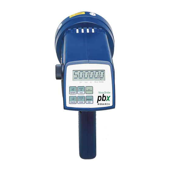
OVERVIEW The Phaser-Strobe pbx is an extremely sophisticated instrument with many features, yet remains simple to operate. Select only the features you need. 1.1 Display Panel / Definition of Buttons The display panel consists of a backlighted liquid crystal display with six numeric digits on top and five alphanumeric digits on the bottom, which indicate modes, flash rates, etc. - Page 6 Below the display are six membrane buttons which control the operation of the stroboscope. Multiply Flash Rate by 2 ALT Function - starts menu (see section 3.0) Hold when powering up to show all segments, then rev # and display test Divide Flash Rate by 2 Hold when powering up to reset factory defaults DISPLAY/TACH...
-
Page 7: Preparation For Use
8.3 External Power Supply/Charger). 2.2 Input / Output Connections The Phaser-Strobe pbx has input and output jacks on the left side of the stroboscope. These can be used for external triggering or synchronization (daisy chaining two or more strobes). These jacks accept 1/8"... - Page 8 Common (GND) Signal Input +6V Out to +6V Out to Sensor Sensor Common Signal Input (GND) Figure 2 Input Connector Detail (Stereo plug) Common Pulse Output (GND) from Strobe Common Pulse Output (GND) from Strobe Figure 3 Output Connector Detail (Mono plug) The optional ROS-P (Remote Optical Sensor), MT-190P (Magnetic), or IRS-P (Infrared) sensors may also be used to trigger the unit.
-
Page 9: Menu
With no external input, the output jack (▼pointing away from socket) provides a TTL compatible pulse from the strobe’s internal oscillator. If an external input is applied, the output pulse is in sync with the input pulse. This output pulse may be used to trigger a second stroboscope synchronously to illuminate larger areas. -
Page 10: Operation
NOTE: Unit must power down completely (OFF will be displayed and then disappear) before unit will power on again. This is normal operation. There are five (5) operating modes for the Phaser-Strobe pbx. These are Internal, External Input, External Phase Delay, External Time Delay, and Auto (Virtual RPM). - Page 11 To change the flash rate: With the power on, turn the knob counter clockwise to increase the flash rate and clockwise to decrease it. The knob is velocity sensitive. Turn the knob slowly to have each click equal to 0.01 FPM. Turning the knob more quickly will adjust the FPM by larger steps.
- Page 12 Example: A 3-bladed fan is spinning at 3600 RPM. The strobe is flashing at 3600 FPM. Press the ALT FUNCTION button to display ALT. Then turn the knob counter clockwise 2 clicks. The strobe will now flash at 10,800 FPM (effectively 3600 times 3). The fans blades will be all superimposed on each other.
-
Page 13: Internal Mode - Tach Frequency Generator
To adjust the Phase Delay: 1. Press the PHASE DELAY button. PHASE will be displayed on the bottom line and the current flash rate will be displayed on the top line. 2. Turn the tuning knob to adjust the location (phase) of the reference mark. -
Page 14: Tachometer Mode - External Input Required
4.4 Tachometer Mode - External Input Required When an external input is supplied to the unit and the strobe is put in the Tachometer Mode, the unit will read the signal from the external input (sensor) and display the reading on the LCD without flashing the lamp. -
Page 15: Power Up Features
To enter one of the External Delay Modes: 1. Plug an external input into the unit. 2. Press the PHASE DELAY button to cycle to the desired mode. 3. Use knob to adjust delay/angle (phase, time or virtual RPM). To exit the External Delay Mode: 1. -
Page 16: Using The Stroboscope To Measure Rpm
USING THE STROBOSCOPE TO MEASURE RPM The primary use for a stroboscope is to stop motion for diagnostic inspection purposes. However the stroboscope can be used to measure speed (in RPM/RPS). In order to do this several factors need to be considered. First, the object being measured should be visible for all 360°... - Page 17 Stopped Image 1/4 times 1/2 times 1 time 2 times 3 times 4 times Flash Rate (FPM) 1250 2500 5000 10000 15000 20000 Example: Object Rotating at 5000 RPM If the speed is outside the full scale range of the stroboscope (20,000 FPM), it can be measured using the method of harmonics and multipoint calculation.
-
Page 18: Limitations Of Remote Optical Sensors
If the ROS is positioned near the strobe, the light from the strobe may cause the ROS to trigger the stroboscope at the wrong time, especially when using a delayed flash mode. The Phaser-Strobe pbx has an Input Blanking feature to allow it to ignore this false trigger. - Page 19 The lamp can be replaced by using just a pocket screwdriver. It is not necessary to remove any screws to replace the lamp. To change the lamp: Push apart the two tabs on the side of the reflector housing and remove the lens using a small screwdriver to help pry one tab and lift the lens.
-
Page 20: Fuse
Under normal operating conditions, the fuse within the stroboscope should never blow. Examples of abnormal operating conditions would be foreign materials entering the strobe, such as water, pulp, ink, etc. The Phaser-Strobe pbx has a replaceable fuse, which will reset once conditions are normal again. -
Page 21: Battery And Power Supply Specifics
BATTERY AND POWER SUPPLY SPECIFICS The Phaser-Strobe pbx is fitted with rechargeable NiMH (Nickel Metal Hydride) batteries. These batteries contain fewer toxic metals than NiCd (Nickel Cadmium) and are currently classified “environmentally friendly”. They also have 30% more capacity than NiCd batteries of the same size. -
Page 22: Charging The Batteries
The unit may be recharged at any time. You do not need to wait until the low battery condition is indicated. To charge the Phaser-Strobe pbx with the power supply/charger: 1. Release the trigger so the strobe is off. 2. Plug the charger cable into the charger socket (located below the display panel behind the handle). -
Page 23: Battery Disposal
8.4 Battery Disposal Prior to disposing of the Phaser-Strobe pbx, the user must remove the Nickel-Metal Hydride batteries. To do this, remove the lens, reflector and lamp as detailed in the Lamp Replacement section. This will expose four (4) screws that must be removed so the reflector housing can be dismantled. - Page 24 External Modes Phaser-Strobe pbx TTL compatible (24V pk max), 0.5 μsec min. External Input pulse width, positive or negative edge-triggered (1/8" phone plug) (menu selectable) General Time Base Ultra-stable crystal oscillator LCD with 6 numeric 0.506 in. [12.85 mm] high Display digits and 5 alphanumeric 0.282 in.
-
Page 25: Compliance
104°F [40°C] *Specifications are subject to change without notice. 9.1 Compliance Phaser-Strobe pbx units are compliant with U.S. Department of Energy’s energy conservation standards specified in the Code of Federal Regulations 10 CFR 430.32(z) and are registered in the DoE CCMS database. -
Page 26: Accessories, Sensors And Replacement Parts
10.0 ACCESSORIES See Accessories webpage for details. Model Description 6280-040 CC-7 Standard Latching Carrying Case with provision for accessories 6280-041 SPC-1 Splash-proof Protective Cover 6280-048 Protective Rubber Protective Rubber Cover fits over reflector Cover housing to protect against accidental drops and infiltration of contaminants 6280-034 C-4027... - Page 27 SENSORS Model Description 6180-029 ROLS-P Remote Optical Laser Sensor with 8 ft. [2.5 m] cable for triggering strobe 6180-057 ROS-P Remote Optical Sensor with 8 ft. [2.5 m] cable for triggering strobe 6180-057-25 ROS-P-25 Remote Optical Sensor with 25 ft. [7.6 m] cable for triggering strobe 6180-020 IRS-P...
- Page 28 The Professional’s Choice Monarch Instrument is committed to excellence and quality in manufacturing, sales, and service. ™ Track-It Data Loggers Panel Tachometers Portable Tachometers Frequency Portable Strobes Fixed Mounted Converters Strobes DataChart ™ Paperless Speed Sensors Recorders 15 Columbia Drive, Amherst NH 03031 USA Tel.: (603) 883-3390 // Fax: (603) 886-3300...
Need help?
Do you have a question about the Phaser-Strobe pbx and is the answer not in the manual?
Questions and answers