
Related Manuals for LDS Dactron PHOTON+


Summary of Contents for LDS Dactron PHOTON+
- Page 1 PHOTON Dynamic Signal Analysis System System Guide Rev. 1.00 System Installation Maintenance Calibration Troubleshooting LDS-Dactron Phone: (608) 821-6600 E-mail: technical.support@dactron.spx.com Web Site: www.lds-group.com...
- Page 2 The user of the software assumes the entire risk of use of the software and the results obtained from use of the software. LDS shall not be liable for any incidental or consequential damages, including loss of data, lost profits, cost of cover or other special or indirect damages.
-
Page 3: Table Of Contents
Table of Contents Table of Contents Introduction ......................1 System Description....................1 Options........................2 System Hookups and Status Indicators ..............2 Specifications......................5 Safety and Equipment Protection ................. 7 Safety Summary ....................... 7 Danger Warnings...................... 8 Power and Environmental Requirements ............9 Power Requirements.................... -
Page 5: Introduction
Introduction 1 Introduction This manual provides instructions on installing, maintaining, and ™ Dynamic Signal Analysis System. It also calibrating a PHOTON provides information on power and environmental requirements and safety considerations. Any person responsible for installing, maintaining or calibrating the system should be fully familiar with the contents of this manual. -
Page 6: Options
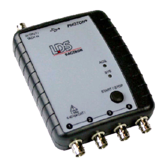
Introduction capture and SRS analysis, swept sine analysis. The can also be PHOTON used for data recording and post analysis. The System comes PHOTON standard with two inputs with ICP® sensor power, an output signal source, a storage case, a 6’ (1.83 m) USB Type A to Type B cable, a user manual (on CD), installation CD, calibration data CD, and a one year warranty covering parts and labor. - Page 7 Introduction Warning Do not connect analog voltage signals exceeding +36 Volts to the input channel or the system electronics may be damaged. Front view of the PHOTON showing the BNC Connectors for Four Input Channels Rear view of the showing the BNC connector forOutput/Tach-in and the PHOTON USB Cable Port.
- Page 8 Introduction Two LED’s on the top of the unit provide status indication: ACQ – flashes when the system is acquiring data. SYS – lit when the DSP is powered. The START/STOP button can be used to remotely start or stop a measurement (when using RT Pro software) Top view of the PHOTON...
-
Page 9: Specifications
Introduction Specifications Inputs Analog channels Two standard, expandable to four channels. All are differential inputs with 1M Ohm impedance. Setup allows per channel selection of gain (x0.01, .0.1, x1, x10), transducer sensitivity, sensor type (e.g., acceleration, force, pressure, etc.), and coupling (AC, DC, ICP Electronics Differential amplifier, programmable gain amplifier, anti-aliasing filters, and 24-bit Analog to Digital Converter (ADC). - Page 10 Any changes or modifications to this equipment not expressly approved by LDS- Dactron could void the user's authority to operate this equipment. All Specifications subject to change without notice.
-
Page 11: Safety And Equipment Protection
Do Not Substitute Parts or Modify the System Because of the danger of introducing additional hazards, do not install substitute parts or perform any unauthorized modification to the system. Return the system to LDS-Dactron for service and repair to ensure that safety features are maintained. System Guide... -
Page 12: Danger Warnings
Safety and Equipment Protection Danger Warnings The warning messages below, and throughout this guide, are important notices regarding safe system operation and system protection. Instructions given by these warning must be followed to ensure safety for both personnel and equipment. Warning Dangerous voltages may be present in the system. -
Page 13: Power And Environmental Requirements
2.5 watts at 5 volt DC is equivalent to 500mA of electrical current. Some PC USB-controllers provide the electrical current information. Below is a bitmap showing the power management of the USB Root Hub with a LDS-Dactron under typical operation: PHOTON... -
Page 14: Usb Cable Requirements
Original Packaging Use the original factory packaging containers to return ship the system to LDS-Dactron for Calibration or service. If the system is being returned to LDS-Dactron for service, attach a tag indicating the return merchandise authorization (RMA) number provided by LDS-Dactron customer support, type of service required, return address, system model name, and serial number. - Page 15 Power and Environmental Requirements 3. Use a layer of shock absorbing material 3 to 4 inches (70 to 100 mm) thick around all sides of the system to provide firm cushioning and prevent movement inside of the container. Protect the control panel with cardboard.
-
Page 16: System Installation
System Installation 4 System Installation Step 1: PHOTON + Driver Installation Instructions communicates with the PC through a USB PHOTON connection. This requires Windows driver software to enable the USB connection. The USB is a “plug and play” device which means that after the driver is initially installed, the configuration of the driver is automatically launched every time the device is plugged into the USB port. - Page 17 System Installation 3. Plug the USB cable into the and the PC. PHOTON The PC will auto detect the presence of the new hardware and launch the “Add New Hardware Wizard.” Note the dialog boxes shown below are from Windows XP. The dialogs for Windows Vista will vary slightly.
- Page 18 System Installation 6. If the files are not automatically located, they are named Photon.sys and Photon.inf and are in the root directory of the installation CD ROM. 7. Select, “Continue Anyway” when the Windows Logo Testing message appears. System Guide PHOTON...
-
Page 19: Step 2: Installing Application Software On The Pc
Pro Dynamic Signal Analysis Series” User Guide, “Installation and Setup Procedure”, for complete details on installation of application software. is now ready to run. Start the LDS-Dactron PHOTON application software from the host PC then you will be ready to use the application software. - Page 20 System Installation 2. The next screen that appears is the hardware initialization screen, which shows the progress of the system firmware download into the ’s Digital Signal Processor. PHOTON 3. Once the DSP code downloading is finished, the calibration file import prompt will appear. 4.
-
Page 21: Updating The Device Driver
RT Pro User Guide (included on a CD ROM that arrived with your ) for further instructions. PHOTON Updating the Device Driver To update the LDS-Dactron device driver follow these PHOTON instructions. 1. Connect the to the PC with a USB cable. -
Page 22: Uninstall The Device Driver
System Installation select the “LDS-Dactron Photon (USB) device”. Click on the Properties button. 6. Choose the Driver tab from the LDS-Dactron Photon (USB) device Properties dialog. 7. Click on the “Update Driver…” button. 8. Follow the instructions and select the new device driver supplied by LDS-Dactron. - Page 23 Click on the Hardware tab and then the Device Manager button. b. Scroll down to Universal Serial Bus controllers, click the “+” icon to expand the selection and right click on “LDS-Dactron Photon USB device”. Select Uninstall from the pop up menu.
- Page 24 System Installation c. Click OK to confirm the device removal. System Guide PHOTON...
- Page 25 System Installation d. Optional: After you remove the device, you may wish to manually delete the following 4 files: C:\WINDOWS\INF\OTHER\PHOTON.INF C:\WINDOWS\SYSTEM32\DRIVERS\PHOTON.SY C:\WINDOWS\INF\OEM#.INF - There may be several #s, e.g., OEM0.INF, OEM1.INF, OEM2.INF, etc... You can open each OEM#.INF file and find the one that lists “Photon”...
-
Page 26: Maintenance
PHOTON+ System. There are no operator settable controls or adjustments inside the PHOTON+ . If you are having a problem with your + System, please contact PHOTON your local LDS Test and Measurement support center. System Guide PHOTON... -
Page 27: Calibration
Once this calibration data is stored, the input measurement and the signal source can be adjusted back to the most accurate value. The LDS-Dactron system uses sigma-delta A/D and D/A converters and an anti-aliasing filter with a very high cutoff frequency. As a result, the amplitude characteristics of the input and output are not frequency dependent. -
Page 28: Calibration Tools
0.25%. The AC bandwidth for the voltmeter should be higher than 10 kHz. The voltmeter accuracy should be 0.25% or better in order to ensure that the LDS-Dactron system is calibrated to an accuracy of ±1% (about ±0.1dB). Generally, the calibration meter’s System Guide... -
Page 29: Install The Calibration Software
Calibration accuracy should be four times higher than the system being calibrated. Install the Calibration Software Insert the Install CD into the CD drive. The CD will then automatically spin up and launch the setup routine. From the installation master menu choose “Signal Analysis Series” then choose the “... - Page 30 Calibration Connect Cables with and Start Software PHOTON Cable Connection for Calibration Connect the BNC cables to all input channels and the OUTPUT channel at one end. Connect all the other ends together with BNC T ports. Connect this cable harness to a voltmeter that is certified to the accuracy standard described above (0.25%).
- Page 31 Calibration Select after the appropriate information has been entered. This will open the normal Calibration screen and dialog informing you to allow the Front-End DSP Box to warm up for at least 10 minutes; click on OK to access the Calibration screen. Before pressing the button, Start measure the DC voltage offset on the OUTPUT channel.
- Page 32 Calibration DC Measurement for Offset Calibration You will also be requested to measure the RMS value of the output at the AC 10 Volt full-scale range and type it into the dialog box. Please make sure that the voltmeter is switched to AC measurement. This concludes the calibration of the OUTPUT channel.
- Page 33 Calibration Input Channel Calibration The input channels are calibrated automatically. The system will now use the calibrated OUTPUT channel as the signal source. The gain error and offset estimation are calculated automatically for all the input range settings. The input calibration process depends on an accurately calibrated OUTPUT channel.
- Page 34 Calibration AC Measurement for the Gain Validation After validation, both the offset and gain error should be within tolerance. The pass/no-pass tolerance used during the validation is: 10 volt range: 1% of the Full Scale 1.0 volt range: 2% of the Full Scale Low-voltage Range Calibration has low voltage input ranges of 0.1 V and 0.01 V.
- Page 35 Calibration … Cable Connection for Low-voltage Range Calibration The dialog boxes below ask for a measurement and entry of the DC and AC reading from the meter. These measurements will be used for the Output Channel calibration so that the low voltage Input Channel calibration is provided with an accurately calibrated signal source.
- Page 36 Calibration AC Measurement for Low-voltage Range Gain Calibration After validation, both the offset and gain error should be within tolerance. The pass/no-pass tolerance used during the validation is: 0.1 volt range: 1% of the Full Scale 0.01 volt range: 1% of the Full Scale Low-voltage Range Calibration Result Validation The Calibration Result Validation described previously will be repeated for the Low-voltage Ranges of 0.1 V and 0.01 V.
- Page 37 Calibration DC Measurement for the Low-voltage Range Offset Validation AC Measurement for the Low-voltage Range Gain Validation System Guide PHOTON...
-
Page 38: Calibration Data File And Report
Calibration Calibration Data File and Report At the end of calibration, a dialog box showing the calibration report will be opened for review. The calibration data file and a text report are saved in the “DactronCalib” directory. You can view the calibration report in text mode at any time. -
Page 39: System Troubleshooting
System Troubleshooting 7 System Troubleshooting The diagram below shows the structured layers of the LDS-Dactron System. Each layer generates and sends a message to the PHOTON system user interface in the event of an error condition. These messages aid in diagnosing and resolving problems. -
Page 40: Check If Usb Driver Is Installed Correctly
System Troubleshooting Follow the instructions provided to re-establish communication with the . Selecting “Ignore” will initialize RT Pro Playback, for offline PHOTON data analysis. Check if USB driver is installed correctly To determine if the driver software has been installed and if the PC recognizes the , first connect the to the PC with a... - Page 41 “LDS-Dactron Photon (USB) device” in the list as shown below. The LDS-Dactron Photon USB device driver will only be listed if the hardware is connected to the PC via the USB cable. If the...
-
Page 42: Failure To Initialize The Photon
Device Manager PHOTON list. If the LDS-Dactron Photon USB device driver is not listed and the is plugged in then the driver may not be installed correctly. In PHOTON this case, try to reinstall, or update, the device driver. This may also be a... -
Page 43: Inadequate Power Supplied To The Photon
• The SYS led flashes then becomes dim or goes dark when the is connected to the PC with a USB cable. PHOTON • The LDS-Dactron Photon (USB) device Driver was installed and the is connected to the PC by a USB device, but the driver is PHOTON not listed on the Device Manager list under the System Control Panel. -
Page 44: Windows Application Software Failure
System Troubleshooting Windows Application Software Failure If any Windows application or DSP software modules are missing the following type of error message is displayed. Follow the instructions provided to fix this problem. System Guide PHOTON... -
Page 45: Limited Warranty Statement
LDS warrants to you, the Buyer, that LDS hardware, accessories and supplies will be free from defects in material and workmanship, for a period of one year from date of shipment. If LDS receives notice of such defects during the warranty period, LDS will, at its option, either repair or replace products which prove to be defective. - Page 46 Limited Warranty Statement ASSISTANCE If you are unable to solve a problem with your LDS-Dactron product, contact your LDS Test and Measurement Representative. To locate the LDS Representative in your area refer to LDS web site www.lds- group.com. You can also contact LDS-Dactron directly using the contact information on the cover page.
-
Page 47: Manual Revision History
9 Manual Revision History Date Manual Version Contents added into the Manual in this version 22 Feb 1.00, 43 pages PHOTON+ Product Release 2008 System Guide PHOTON... -
Page 48: Index
10 Index Calibration ............23 RT Pro ............15 Danger Warnings..........8 Safety ............1, 7 Shipment ............10 Software Option ..........2 Specifications ........... 5 Environmental Requirements ......10 Storage ............10 System Description .......... 1 System Installation ......... 12 Hardware Option ..........
Need help?
Do you have a question about the Dactron PHOTON+ and is the answer not in the manual?
Questions and answers