Table of Contents
Advertisement
Available languages
Available languages
Quick Links
WARNING: If the information in this manual is not
followed exactly, a fire or explosion may result causing
property damage, personal injury or loss of life.
— Do not store or use gasoline or other flammable va-
pors and liquids in the vicinity of this or any other
appliance.
— WHAT TO DO IF YOU SMELL GAS
• Do not try to light any appliance.
• Do not touch any electrical switch; do not use any
phone in your building.
• Immediately call your gas supplier from a neighbor's
phone. Follow the gas supplier's instructions.
• If you cannot reach your gas supplier, call the fire
department.
— Installation and service must be performed by a quali-
fied installer, service agency or the gas supplier.
INSTALLER: Leave this manual with the appliance.
CONSUMER: Retain this manual for future reference.
Before returning to your retailer, call our customer service department at
Questions, problems, missing parts?
1-800-229-5647, 8:00 am - 5:00 pm EST, Monday through Friday
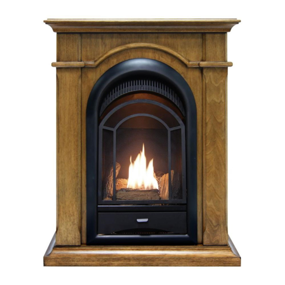
VENT-FREE GAS
FIREPLACE INSERT
OWNER'S OPERATION AND
INSTALLATION MANUAL
MODEL
VFF15NLA
PFS
®
US
Advertisement
Chapters
Table of Contents

Related Manuals for EmberGlow VFF15NLA


Summary of Contents for EmberGlow VFF15NLA
- Page 1 VENT-FREE GAS FIREPLACE INSERT OWNER’S OPERATION AND INSTALLATION MANUAL MODEL VFF15NLA ® WARNING: If the information in this manual is not followed exactly, a fire or explosion may result causing property damage, personal injury or loss of life. — Do not store or use gasoline or other flammable va- pors and liquids in the vicinity of this or any other appliance.
-
Page 2: Table Of Contents
TABLE OF CONTENTS Safety ............3 Operation ..........17 Qualified Installing Agency ......4 Inspecting Burners........20 Specifications ..........5 Care And Maintenance ......21 Product Features ........5 Troubleshooting ........23 Local Codes..........5 Replacement Parts ........27 Unpacking..........6 Accessories .......... -
Page 3: Safety
SAFETY IMPORTANT: Read this owner’s WARNING: Young children manual carefully and completely should be carefully supervised before trying to assemble, op- when they are in the same room erate, or service this heater. as the appliance. Toddlers, Improper use of this heater can young children and others may cause serious injury or death from be susceptible to accidental... -
Page 4: Qualified Installing Agency
SAFETY 8. Do not use heater if any part has been WARNING: You must operate under water. Immediately call a qualified this heater with screen in place. service technician to inspect the room heater and to replace any part of the Any safety screen or guard control system and any gas control which removed for servicing an appli-... -
Page 5: Specifications
SPECIFICATIONS Model VFF15NLA Gas Type Natural Gas Propane Gas Maximum Input Rating 15,000 Btu/Hr 15,000 Btu/Hr Minimum Input Rating 7,000 Btu/Hr 11,000 Btu/Hr Pressure Regulator Setting 4" W.C. 9" W.C. Max. 9.5" Max. 14" Inlet Gas Pressure* (inches of water) Min. -
Page 6: Unpacking
UNPACKING 1. Remove top inner pack. 7. Remove log set by cutting plastic ties. 2. Tilt carton so that heater is upright. 8. Carefully unwrap log. 3. Remove protective side packaging. 9. Check for any shipping damage. If heater or log is damaged, promptly inform your 4. -
Page 7: Air For Combustion And Ventilation
AIR FOR COMBUSTION AND VENTILATION WARNING: This heater shall WARNING: This heater shall not be installed in a confined space not be installed in a room or or unusually tight construction space unless the required vol- unless provisions are provided ume of indoor combustion air for adequate combustion and is provided by the method de-... - Page 8 AIR FOR COMBUSTION AND VENTILATION VENTILATION AIR Ventilation Air From Inside Building Ventilation Air From Outdoors Provide extra fresh air by using ventilation This fresh air would come from an adjoining grills or ducts. You must provide two perma- unconfined space. When ventilating to an nent openings: one within 12"...
-
Page 9: Installation
INSTALLATION IMPORTANT: Vent-free heaters add moisture NOTICE: This heater is intended to the air. Although this is beneficial, installing for use as supplemental heat. heater in rooms without enough ventilation air Use this heater along with your may cause mildew to form too much moisture. primary heating system. - Page 10 INSTALLATION GAS SELECTION Insert Gas Fitting Insert Gas Fitting This appliance is factory for Propane Gas for Natural Gas preset for propane gas. No changes are required for connecting to propane. Only a qualified installer or service technician can perform gas selec- tion and connecting to gas supply.
- Page 11 INSTALLATION 3. Apply thread sealant to the threads on the connection fitting. While pushing in, rotate the fitting clockwise until the threads engage the regulator. After the fitting has been hand tightened into the regulator use a wrench to complete tightening of the fitting.
- Page 12 INSTALLATION BUILT-IN FIREPLACE INSTALLATION WARNING: Do not allow any combustible materials to overlap the firebox front. WARNING: Do not allow combustible or noncombustible materials to cover any necessary openings like louvered slots. 1/4" Clearance to Facia WARNING: Never modify or 3/8"...
- Page 13 INSTALLATION 3. Attach gas line to fireplace gas regulator. See Connecting to Gas Supply, page 13. 4. Check all gas connections for leaks. See 90° Checking Gas Connections, page 15. IMPORTANT: When finishing your firebox, combustible materials such as wall board, gypsum board, sheet rock, drywall, plywood, etc, must have 1/2"...
- Page 14 INSTALLATION CONNECTING TO GAS SUPPLY WARNING: A qualified ser- CAUTION: For propane gas, vice technician must connect never connect heater directly heater to gas supply. Follow all to the gas supply. This heater local codes. requires an external regula- tor (not supplied). Install the external regulator between the WARNING: This appliance heater and propane gas supply.
- Page 15 INSTALLATION IMPORTANT: Install an equipment shutoff If you do not reduce incoming gas pressure, valve in an accessible location. The equip- heater regulator damage could occur. Install ment shutoff valve is for turning on or shutting external regulator with the vent pointing down off the gas to the appliance.
- Page 16 INSTALLATION CHECKING GAS CONNECTIONS Test Pressures Equal To or Less Than WARNING: Test all gas piping 1/2 PSIG (3.5 kPa) and connections for leaks after 1. Close equipment shutoff valve (see Fig- installing or servicing. Correct ure 15). all leaks at once. 2.
- Page 17 INSTALLATION PRESSURE TESTING HEATER GAS CONNECTIONS 1. Open equipment shutoff valve (see Figure 17, page 16). Apply a noncorrosive leak 15, page 16). detection fluid to all joints. Bubbles form- ing show a leak. 2. Open main gas valve located on or near gas meter for natural gas or open propane 5.
-
Page 18: Operation
INSTALLATION BATTERY INSTRUCTIONS CAUTION: Do not dispose of batteries in fire, batteries may explode or leak. Battery • Battery is included. Positive • Remove battery when depleted. • Be sure to observe proper polarity (+/-) when installing or replacing the battery. Damage due to improper battery installation may void the warranty on the product. - Page 19 OPERATION LIGHTING INSTRUCTIONS Note: If pilot does not stay lit, refer to WARNING: You must oper- Troubleshooting, pages 24 though 27. ate this heater with the screen Also contact a qualified service technician in place. Make sure screen is or gas supplier for repairs. Until repairs are made, light pilot with match.
- Page 20 OPERATION THERMOSTAT CONTROL OPERATION The thermostatic control used on this model temperature), then back counterclockwise differs from standard thermostats. Standard , just until the flame reignites. Leave the thermostats are set to a specific tempera- knob in this position. As the room temperature ture such as 72°.
-
Page 21: Inspecting Burners
INSPECTING BURNERS IMPORTANT: Owner’s should check pilot flame pattern and burner flame pattern often. Incorrect flame patterns indicate the need for cleaning (see Care and Maintenance, page 22) or service. WARNING: Only a qualified service person should service and repair heater. This includes maintenance requiring replacement or alteration of components. -
Page 22: Care And Maintenance
CARE AND MAINTENANCE WARNING: Turn off heater and let cool before servicing. CAUTION: You must keep control areas, burner, and circulating air passageways of heater clean. Inspect these areas of heater before each use. Have heater inspected yearly by a qualified service techni- cian. - Page 23 CARE AND MAINTENANCE ODS/PILOT Ignitor Natural Gas Thermocouple CAUTION: Never use a wire, Electrode Burner needle, or similar object to clean Propane Gas Burner ODS/pilot. This can damage ODS/pilot unit. Use a vacuum cleaner, pressurized air, or a Pilot Air small, soft bristled brush to clean.
-
Page 24: Troubleshooting
TROUBLESHOOTING WARNING: If you smell gas: • Shut off gas supply. • Do not try to light any appliance. • Do not touch any electrical switch; do not use any phone in your building. • Immediately call your gas supplier from a neighbor’s phone. Fol- low the gas supplier’s instructions. - Page 25 TROUBLESHOOTING Problem Possible Cause Corrective Action When ignitor button is 1. Ignitor electrode is posi- 1. Replace electrode. pressed in, there is no tioned wrong. Ignitor elec- spark at ODS/pilot trode is broken. 2. Ignitor electrode is not con- 2. Replace ignitor cable nected to ignitor cable.
- Page 26 TROUBLESHOOTING Problem Possible Cause Corrective Action Burner(s) does not light 1. Burner orifice is clogged. 1. Clean burner orifice (see after ODS/pilot is lit Care and Maintenance, page 22) or replace burner orifice. 2. Burner orifice diameter is too 2. Replace burner orifice. small.
- Page 27 TROUBLESHOOTING Problem Possible Cause Corrective Action Heater produces a click- 1. Metal is expanding while 1. This is common with most ing/ticking noise just after heating or contracting while heaters. If noise is exces- burner is lit or shut off. cooling.
- Page 28 PARTS MODEL VFF15NLA www.sureheat.com 200176-01B...
- Page 29 PARTS MODEL VFF15NLA This list contains replaceable parts for your heater. When ordering replacement parts, follow the instructions listed under Replacement Parts on page 30 of this manual. ITEM PART # DESCRIPTION 150PCS102B-02 Screen Assembly 162643-01 Gas Train Assembly PIMDN1-01...
-
Page 30: Replacement Parts
REPLACEMENT PARTS Note: Use only original replacement parts. This will protect your warranty coverage for parts replaced under warranty. PARTS UNDER WARRANTY PARTS NOT UNDER WARRANTY C a l l C u s t o m e r S e r v i c e t o l l f r e e a t C a l l C u s t o m e r S e r v i c e t o l l f r e e a t 1-800-229-5647 to order parts under war- 1-800-229-5647 to order parts not under... -
Page 31: Service Hints
SERVICE HINTS When Gas Pressure Is Too Low • pilot will not stay lit • burners will have delayed ignition • fireplace will not produce specified heat • propane gas supply might be low (propane units only) You may feel your gas pressure is too low. If so, contact your local gas supplier. TECHNICAL SERVICE You may have further questions about installation, operation, or troubleshooting. -
Page 32: Warranty
WARRANTY KEEP THIS WARRANTY Model _______________________________ Serial No. ____________________________ Date Purchased _______________________ Keep receipt for warranty verification. IMPORTANT: We urge you to fill out your warranty information above. Complete with the entire serial number which can be found on the rating plate. Retain this manual for future reference. Always specify model and serial numbers when communicating with customer service. - Page 33 GAS INSERTAR MANUAL DE FUNCIONAMIENTO E INSTALACIÓN DEL PROPIETARIO MODELO VFF15NLA ® ADVERTENCIA: Si la información contenida en este manual no se sigue al pie de la letra, se pueden producir un incendio o una explosión que podrían ocasionar daños a la propiedad, lesiones personales o la pérdida de la vida.
- Page 34 TABLA DE CONTENIDOS Seguridad ..........35 Instalación ..........42 Agencia De Instalación Calificada ... 37 Funcionamiento ........52 Especificaciones ........37 Inspección de los Quemadores ....55 Características Del Producto ....38 Cuidado y mantenimiento ......56 Normas Locales........38 Solución de problemas ......
-
Page 35: Seguridad
SEGURIDAD Gas natural y gas propano: el gas natural IMPORTANTE: Lea este manual del y gas propano son gases inodoros. Al gas propietario cuidadosa y completa- propano se le agrega un agente con olor. El mente antes de intentar ensamblar, olor le ayuda a detectar las fugas de gas. - Page 36 SEGURIDAD Aire para combustión y ventilación en ADVERTENCIA: Debido a las la página 40. Si el calentador continúa altas temperaturas generadas apagándose, consulte Solución de pro- blemas, en la página 58. por este aparato, éste se debe 4. Mantenga todas las entradas de aire del colocar fuera de las rutas de frente y fondo del calentador limpias y paso y alejado de muebles y...
-
Page 37: Agencia De Instalación Calificada
ESPECIFICACIONES Modelo VFF15NLA Tipo de gas Natural Propano Clasificación máxima de entrada 15,000 BTU/Hr 15,000 BTU/Hr Clasificación mínima de entrada... -
Page 38: Características Del Producto
CARACTERÍSTICAS DEL PRODUCTO PILOTO DE SEGURIDAD CONTROL DEL CALOR POR TERMOSTATO El calentador posee un piloto que cuenta con un sistema de apagado de seguridad El control apaga y enciende el quemador de por medio de un sensor de agotamiento de forma automática por ciclos para mantener oxígeno (ODS). -
Page 39: Desempaque
DESEMPAQUE 1. Retire la parte superior del empaque 7. Retire el juego de leños cortando los interno. amarres de plástico. 2. Incline la caja de manera que el calenta- 8. Retire cuidadosamente la envoltura del dor quede en posición vertical. leños. -
Page 40: Aire Para Combustión Y Ventilación
AIRE PARA COMBUSTIÓN Y VENTILACIÓN Los ventiladores de expulsión de aire, las ADVERTENCIA: Este calen- chimeneas, las secadoras de ropa y los apa- tador no debe instalarse en un ratos que queman combustible toman aire de la casa durante su funcionamiento. Usted espacio confinado ni en una debe proporcionar la cantidad adecuada de construcción inusualmente... - Page 41 AIRE PARA COMBUSTIÓN Y VENTILACIÓN AIRE PARA VENTILACIÓN Aire del interior de la construcción Aire del exterior para ventilación para ventilación Proporcione aire fresco adicional mediante Este aire fresco viene de un espacio adyacen- el uso de rejillas o conductos de ventilación. te no confinado.
-
Page 42: Instalación
INSTALACIÓN AVISO: Este calentador está PRECAUCIÓN: Este calen- diseñado para utilizarse como tador crea corrientes de aire calefacción adicional. Use este caliente. Estas corrientes mue- calentador junto con su sistema ven el calor hacia la superficie de calefacción principal. No de las paredes próximas al instale este calentador como calentador. - Page 43 INSTALACIÓN ESPACIO LIBRE PARA Techo MATERIALES COMBUSTIBLES ADVERTENCIA: Usted debe 42" mantener las distancias mínimas Min. que se muestran en la Figura 4. Si Pared Pared puede, proporcione distancias 8" 8" lateral lateral mayores desde el piso, el techo Min. Min.
- Page 44 INSTALACIÓN SELECCIÓN DE GAS Insertar gas montaje Inserte gas montaje Este aparato viene ajustado para Propano gas de Gas Natural de fábrica para gas propano. No se requieren cambios para la conexión a propano. Sólo un instalador o técnico de servicio calificado puede realizar la selección de gas y la conexión al suministro de gas.
- Page 45 INSTALACIÓN 3. Aplique sellador de roscas a las roscas en el accesorio de conexión. Mientras presiona, gire hacia la derecha el ajuste hasta que las roscas se acoplan al regu- lador. Después de la instalación se ha apretado sido parte en el regulador con una llave para completar endurecimiento del accesorio.
- Page 46 INSTALACIÓN INSTALACIÓN DE LA CHIMENEA EMPOTRADA ADVERTENCIA: No permita que materiales combustibles se superpongan a la parte frontal de la cámara de combustión. ADVERTENCIA: No permita que materiales combustibles o no combustibles cubran abertu- ras necesaria tales como ranu- 1/4" Distancia del alero ras de lamas abiertas.
- Page 47 INSTALACIÓN 2. Coloque cuidadosamente la chimenea delante de la abertura sin terminación, con su parte posterior dentro de la abertura de 90° la pared. 3. Conecte la línea de gas al regulador de gas de la chimenea. Consulte Conexión al suministro de gas, página 48. 4.
- Page 48 INSTALACIÓN CONEXIÓN AL SUMINISTRO DE GAS ADVERTENCIA: Una per- PRECAUCIÓN: Para gas sona de servicio capacitada propano, nunca conecte el calen- debe conectar el calentador al tador directamente al suministro suministro de gas. Siga todas de gas propano. Este calentador las normas locales.
- Page 49 INSTALACIÓN Diámetros usuales de tubería de entrada del gas entrante. Debe reducir la presión Utilice tuberías de hierro negro de 3/8" o más del gas entrante de manera que esté entre grandes. La instalación debe incluir la válvula 11" y 14" de c.a. Si no reduce la presión del de cierre del equipo, la unión y el tapón con gas entrante, se pueden producir daños al rosca NPT de 1/8".
- Page 50 INSTALACIÓN REVISIÓN DE LAS CONEXIONES DE GAS 5. Repare todas las fugas inmediatamente. ADVERTENCIA: Después 6. Vuelva a conectar el calentador y la de instalar el calentador o de válvula de cierre del equipo al suministro de gas. Revise las conexiones que se darle servicio, pruebe todas las volvieron a conectar en caso de fugas.
- Page 51 INSTALACIÓN COMPROBACIÓN DE LA PRESIÓN DE LAS CONEXIONES DE GAS DEL CALENTADOR 1. Abra la válvula de cierre del equipo (con- página 50). Aplique en todas las uniones sulte la figura 15, página 50). algún líquido de detección de fugas que 2.
-
Page 52: Funcionamiento
INSTALACIÓN INSTRUCCIONES PARA LAS BATERÍAS Desatornille la tapa del encendedor e instale PRECAUCIÓN: No tire las una batería AAA con el ánodo (+) apuntando pilas al fuego, pueden explotar hacia afuera. Vuelva a colocar la tapa. o tener fugas. • Las baterías están incluidas. Batería •... - Page 53 FUNCIONAMIENTO INSTRUCCIONES DE ENCENDIDO • Si al soltar la perilla de control ésta no ADVERTENCIA: Debe operar regresa a su posición original, llame a este calentador con la rejilla co- un técnico de servicio calificado o a su locada en su lugar. Asegúrese de proveedor de gas para que realicen las reparaciones necesarias.
- Page 54 FUNCIONAMIENTO 8. Gire la perilla de control en sentido con- ADVERTENCIA: Si el tipo trario al de las manecillas del reloj de entrada de gas es NG, ase- para el nivel de calefacción deseado. El gúrese de que el quemador del quemador principal deberá...
-
Page 55: Inspección De Los Quemadores
INSPECCIÓN DE LOS QUEMADORES IMPORTANTE: El propietario debe revisar frecuentemente los patrones de la llama del piloto y de la llama del quemador. Patrones de llama incorrectos indican la necesidad de limpieza o servicio de mantenimiento (consulte Cuidado y mantenimiento, página 56). ADVERTENCIA: Sólo una persona de servicio capacitada debe repararlo o darle servicio. -
Page 56: Cuidado Y Mantenimiento
CUIDADO Y MANTENIMIENTO ADVERTENCIA: Apague el calentador y deje que se enfríe antes de darle mantenimiento. Sólo una persona de servicio capacitada debe repararlo o darle servicio. PRECAUCIÓN: Debe mantener limpias las áreas de control, el quemador y las vias de circulación de aire del calentador. Inspec- cione estas áreas del calentador antes de cada uso. - Page 57 CUIDADO Y MANTENIMIENTO ODS/PILOTO Electrodo del Quemador de PRECAUCIÓN: Nunca utilice encendedor gas natural Termopar un alambre, aguja u objetos Quemador de parecidos para limpiar el piloto/ Gas Propano ODS. Esto puede dañar la unidad de piloto/ODS. Utilice una aspiradora, aire comprimido o Orificio de un cepillo pequeño, de cerdas suaves para entrada de...
-
Page 58: Solución De Problemas
SOLUCIÓN DE PROBLEMAS ADVERTENCIA: Si percibe olor a gas • Cierre el suministro de gas. • No intente encender ningún aparato. • No toque ningún interruptor eléctrico; no use ningún teléfono en el edificio. • Llame inmediatamente a su proveedor de gas desde el teléfono de algún vecino. - Page 59 SOLUCIÓN DE PROBLEMAS Problema Causa Posible Acción Correctiva Cuando se presiona el 1. Electrodo de encendido está 1. Remplace el electrodo del botón del encendedor, no mal colocado. Electrodo de encendedor. hay chispa en el piloto/ encendido está roto. ODS. 2.
- Page 60 SOLUCIÓN DE PROBLEMAS Problema Causa Posible Acción Correctiva El piloto/ODS se en- 1. La perilla de control no está 1. Presione la perilla de control ciende, pero la llama se presionada completamente. completamente. extingue cuando la perilla 2. La perilla de control no se 2.
- Page 61 SOLUCIÓN DE PROBLEMAS Problema Causa Posible Acción Correctiva Llamas amarillas alta 1. No hay suficiente aire. 1. Revise el quemador en bus- durante la combustión ca de polvo y residuos. Si en el quemador. los hay, limpie el quemador (consulte Cuidado y mante- nimiento, en la página 56).
- Page 62 SOLUCIÓN DE PROBLEMAS Problema Causa Posible Acción Correctiva El calentador produce 1. En el calentador se están 1. Abra la ventana para ventilar olores no deseados. quemado vapores prove- la habitación. Deje de utilizar nientes de pintura, fijador los productos que ocasionan para el cabello, pegamentos, el olor mientras el calentador productos de limpieza, pro-...
-
Page 63: Piezas De Repuesto
PIEZAS DE REPUESTO Nota: use sólo piezas de repuesto originales. Esto protegerá la cobertura de su garantía para partes remplazadas bajo la garantía. PIEZAS CON GARANTÍA Por lo general, le pediremos que devuelva la Comuníquese con los distribuidores autoriza- pieza a la fábrica. dos de este producto. -
Page 64: Piezas
PIEZAS MODELO VFF15NLA www.sureheat.com 200176-01B... - Page 65 PIEZAS MODELO VFF15NLA Esta lista contiene las piezas remplazables utilizadas en el calentador. Al hacer un pedido de piezas, siga las instrucciones listadas en Piezas de repuesto en la página 63 de este manual. ITEM PART # DESCRIPTION 150PCS102B-02 Asamblea de pantalla...
- Page 66 NOTES ________________________________________________________________ ________________________________________________________________ ________________________________________________________________ ________________________________________________________________ ________________________________________________________________ ________________________________________________________________ ________________________________________________________________ ________________________________________________________________ ________________________________________________________________ ________________________________________________________________ ________________________________________________________________ ________________________________________________________________ ________________________________________________________________ ________________________________________________________________ ________________________________________________________________ ________________________________________________________________ ________________________________________________________________ ________________________________________________________________ ________________________________________________________________ ________________________________________________________________ ________________________________________________________________ ________________________________________________________________ ________________________________________________________________ ________________________________________________________________ ________________________________________________________________ www.sureheat.com 200176-01B...
- Page 67 NOTES ________________________________________________________________ ________________________________________________________________ ________________________________________________________________ ________________________________________________________________ ________________________________________________________________ ________________________________________________________________ ________________________________________________________________ ________________________________________________________________ ________________________________________________________________ ________________________________________________________________ ________________________________________________________________ ________________________________________________________________ ________________________________________________________________ ________________________________________________________________ ________________________________________________________________ ________________________________________________________________ ________________________________________________________________ ________________________________________________________________ ________________________________________________________________ ________________________________________________________________ ________________________________________________________________ ________________________________________________________________ ________________________________________________________________ ________________________________________________________________ ________________________________________________________________ www.sureheat.com 200176-01B...
-
Page 68: Garantía
GARANTÍA GUARDE ESTA GARANTÍA Modelo __________________________________ Número de serie __________________________ Fecha de compra _________________________ Conserve su recibo para la verificación de la garantía. IMPORTANTE: Le pedimos que complete la información de su garantía antes mencionada. Completo con todo el número de serie que se puede encontrar en la placa de características. Conserve este manual para futuras consultas.
Need help?
Do you have a question about the VFF15NLA and is the answer not in the manual?
Questions and answers