Table of Contents
Advertisement
Quick Links
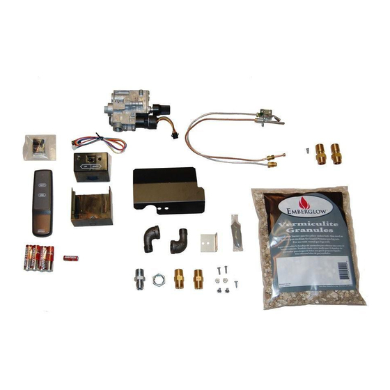
REMOTE CONTROLLED SAFETY PILOT KIT
Supplemental Installation Instructions for use with
NOTE: This kit is for both Natural Gas and LP Gas applications. For LP (Propane) Gas
installation, see additionall LP instructions packaged with necessary hardware.
DO NOT USE THE NATURAL GAS ORIFICE SUPPLIED WITH THIS KIT ON LP
(PROP ANE) GAS INSTALLATIONS! IMPROPER COMBUSTION WILL OCCUR!
Read and follow ALL instructions carefully, as these supplemental Remote Controlled
Pilot Assembly instructions are to be used in conjunction with the General Installation
Instructions supplied with all Vented Natural Gas Log Sets.
20
Part
Description
No.
1
Remote Transmitter
2
Remote Receiver & Hardware
3
Gas Control Valve
4
Straight Flare Fitting, 3/8"
5
Thermocouple lead connection
6
Pilot Line Connection
7
Pilot Burner Assembly
8
Pilot Bracket
National code Requirements mandate the use of a Safety Pilot Valve on all LP (Pro-
pane applications. These regulations MUST be followed on all installations of this type.
MODEL RVS304
Natural Gas Log Sets
IMPORTANT:
3
2
1
17
21
4
Illustrated Parts List
Part
No.
9
Sheet Metal Screw (1)
10
Machine Screw (2)
11
Nut (2)
12
Pilot Orifice Location (NG)
13
Machine Screw 10 x 24 (2)
14
Heat Shield
15
Lock Nut (3/8 NPT)
16
Street Elbow, 90 deg. (2)
12
14
22
8
16
19
15
10
11
9
18
13
LP Burner Media
Description
LP Conversion
7
Items
6
5
Part
Description
No.
17
Heat Shield, Receiver
18
18" Natural Gas Orifice
(Small Center Hole)
19
24" Natural Gas Orifice
(Large Center Hole)
20
Battery,
Receiver AA (3)
21
Battery, T
ransmitter 12v
22
Thread Sealant
Advertisement
Table of Contents

Related Manuals for EmberGlow RVS304


Summary of Contents for EmberGlow RVS304
- Page 1 MODEL RVS304 REMOTE CONTROLLED SAFETY PILOT KIT Supplemental Installation Instructions for use with Natural Gas Log Sets NOTE: This kit is for both Natural Gas and LP Gas applications. For LP (Propane) Gas installation, see additionall LP instructions packaged with necessary hardware.
- Page 2 SINGLE & DUAL SYSTEMS INSTALLATION OF NATURAL GAS PILOT VALVE STOP This Safety Pilot Kit contains a C.S.A Certified Control Valve, which provides a safe and convenient way to ignite and control the flame height on your energy efficient gas log set. Note: Use pipe compound on all male threads to seal joints.
- Page 3 SINGLE & DUAL SYSTEMS INSTALLATION OF NATURAL GAS PILOT VALVE (cont.) E. Connect the two 3/8" Street Elbows (Part #16). Screw the 3/8" threads of the first elbo w into the outlet of the second. Apply pipe compound to the male threads of the elbow and attach it to the control valve outlet. (See Figure 5) Place the hole of the Heat Shield (Part #14) over the elbow and slide it down against the body of the elbow at the point it enters the Gas Control Valve.
- Page 4 LIGHTING YOUR GAS LOGS WITH THE RVS304 SAFETY PILOT KIT Turn the gas control knob counterclockwise to the PILOT position, push the gas control knob IN and hold in for about a minute. This will open the pilot valve and allows gas to flow to the pilot burner.
- Page 5 BATTERY INSTALLATION AND OPERATION INSTRUCTIONS IF YOU CANNOT READ OR UNDERSTAND THESE INSTALLATION INSTRUCTIONS DO NOT ATTEMPT TO INSTALL OR OPERATE This remote control system was developed to provide safe, reliable, user-friendly remote control system for gas heating decorative appliances. The system can be operated manually from the transmitter.
- Page 6 CONNECTING THE RECEIVER TO THE VA LVE KIT Do not install the (4) AA batteries into the receiver until the DC Step Motor is connected to the receiver. • The receiver will calibrate the step motor once the batteries are installed. Connect the 4-pin female connector from the DC step motor to the 4-pin male connector on the wire harness.
- Page 7 TRANSMITTER WALL CLIP The transmitter can be hung on a wall using the clip provided. WALL CLIP SLOT • Wood - Drill 1/8’’ pilot holes and install with screws provided. WALL CLIP • Plaster/Wallboard - Drill 1/4’’ holes, tap plastic anchors in with hammer, then install with the provided screws.
- Page 8 LIMITED WARRANTY Limited Warranty shall apply to the original purchaser at the original installation point only. Pilot, valves and thermocouples are guaranteed for a period of one (1) year under the original manufacturers warranty. General Warranty: This warranty does not apply in the case of improper installation, neglect, accident, misuse or as a result of modifications of the original product.
Need help?
Do you have a question about the RVS304 and is the answer not in the manual?
Questions and answers