
Related Manuals for CPG CK-HPSU212


Summary of Contents for CPG CK-HPSU212
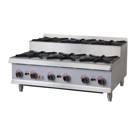
- Page 1 USER MANUAL Gas Step Up Hot Plate MODELS: CK‐HPSU212, CK‐HPSU424, 06 / 2017 CK‐HPSU636 1 ...
- Page 2 IMPORTANT FOR FUTURE REFERENCE Please complete this information and retain this manual for the life of the equipment. For Warranty Service and/or parts, this information is required. Model Number ...
-
Page 3: Table Of Contents
Congratulations on your purchase of CPG commercial cooking equipment. CPG takes pride in the design and quality of our products. When used as intended and with proper care and maintenance, you will experience years of reliable operation from this equipment. To ensure best results, it is important that you read and follow the instructions in this manual carefully. TABLE OF CONTENTS: ITEM PAGE ITEM PAGE ... -
Page 4: Safety Precautions
LOCATION OF DATA PLATE The data plate is located on the side panel. IMMEDIATELY INSPECT FOR SHIPPING DAMAGE Equipment should be examined for damage before and during unloading. The freight carrier has assumed responsibility for its safe transit and delivery. If equipment is received damaged, either apparent or concealed, a claim must be made with the delivering carrier. A) Apparent damage or loss must be noted on the freight bill at the time of delivery. It must then be signed by the carrier representative (Driver). If this is not done, the carrier may refuse the claim. The carrier can supply the necessary forms. B) If concealed damage or loss is not apparent until after equipment is uncrated, a request for inspection must be made to the carrier within 15 days. The carrier should arrange an inspection. Be ... -
Page 5: General Installation Instructions
GENERAL INSTALLATION INSTRUCTIONS Ensure gas supply and gas type, as shown on unit nameplate, match. Unit installation must conform with the National Fuel Gas Code, ANSI Z223.1/NFPA 54, the National Gas Installation Code, CSA‐B149.1, or the Propane Installation Code, CSA‐B149.2 as applicable and in accordance with local codes. Screw legs into the permanently fastened nuts on the four corners of the unit and tighten by hand. Level the unit by turning the adjustment screw at the bottom of each leg. Do not slide unit with legs mounted, lift if necessary to move unit. Pipe threading compound must be resistant to the action of liquefied petroleum gases. Caution: DO NOT use an open flame to check for leaks. Check all gas piping for leaks with a soap and water solution before operating unit. THESE UNITS ARE SUITABLE FOR INSTALLATION ON NON‐COMBUSTIBLE SURFACES ONLY. Combustible clearances: 6" sides (152 mm) 6" rear (152 mm) 4" floor (102 mm) Noncombustible clearances: 0" sides (0 mm) 0" rear (0 mm) 4" floor (102 mm) Do not obstruct the flow of combustion and ventilation air, under the unit by the legs or behind the unit by the flue. Adequate clearance for air openings into the combustion chamber is required. Do not place objects between the bottom of the unit and the counter top. There must be adequate clearance for removal of the front panel. All major parts except the burners are removable through the front if the gas line is disconnected. ... -
Page 6: Conversion
CONVERSION Instructions are for conversion from Natural Gas to Propane (L.P.) on all models. The conversion should be done before connecting the unit to the gas supply. Units are shipped from the factory equipped for use with natural gas. Orifices necessary for LP (propane) are provided in a bag tied to the valve on the front panel. 2. Remove the burner from the top 1. Remove the knobs and front panel. ... -
Page 7: Lighting Instructions
LIGHTING INSTRUCTIONS Lighting pilot The pilot light on the appliance has been set at the factory. A screwdriver may be required for the first lighting to adjust the flame for your elevation. 1. Turn off the manual valve and wait 5 minutes to clear the gas. 2. Turn all knobs to the "OFF" position. 3. Hold an ignition source (match) at the pilot. When the flame is established, remove the ignition source. 4. Turn the burner knobs to "ON". If the burner does not ignite, promptly open the pilot valve more. If the pilot flame appears larger than necessary, turn it down and reset burner ignition. The pilot flame should be as small as possible but large enough to guarantee reliable ignition of the burners when the knobs are turned to "ON". ... -
Page 8: Cleaning & Maintenance
CLEANING & MAINTENANCE CAUTION: Use only non‐abrasive cleaners. Abrasive cleaners could scratch the finish of your unit, marring it’s appearance and making it susceptible to dirt accumulation. Do not use steel wool, other abrasive cleaners or cleaners/sanitizers containing chlorine, iodine, ammonia or bromine chemicals as these will deteriorate the stainless steel and glass material and shorten the life of the unit. Daily 1. Thoroughly clean back, sides, top and front of unit. 2. Clean grates daily. Weekly 1. Clean unit thoroughly. Clean stainless steel or chromed surfaces with a damp cloth and polish with ... -
Page 9: Explosion View Drawing
EXPLOSION VIEW DRAWING MODEL: CK‐HPSU424 ... -
Page 10: Spare Parts List
Spare Parts List DESCRIPTION MODEL CODE CK-HPSU212 Dial CK-HPSU424 06.05.1472429 CK-HPSU636 CK-HPSU212 01.05.1029410 Tray CK-HPSU424 01.05.1029318 CK-HPSU636 01.05.1029365 CK-HPSU212 Foot CK-HPSU424 01.02.1005373 CK-HPSU636 CK-HPSU212 Regulator CK-HPSU424 01.22.1069501 CK-HPSU636 CK-HPSU212-NAT CK-HPSU424-NAT 01.20.1068643 CK-HPSU636-NAT Orifice CK-HPSU212-LPG CK-HPSU424-LPG 01.20.1068652 CK-HPSU636-LPG CK-HPSU212 Burner CK-HPSU424 06.05.1472521... - Page 11 CK-HPSU212 Pilot pipe assy.-Front CK-HPSU424 01.24.1071015 CK-HPSU636 CK-HPSU212 Main pipe assy.-Front CK-HPSU424 06.05.1473192 CK-HPSU636 CK-HPSU212 Main pipe assy.-Rear CK-HPSU424 06.05.1473193 CK-HPSU636 CK-HPSU212 Valve connection CK-HPSU424 66.04.1820085 CK-HPSU636 CK-HPSU212 Valve CK-HPSU424 01.20.1068502 CK-HPSU636 CK-HPSU212 Pilot valve CK-HPSU424 01.20.1068508 CK-HPSU636 ...
Need help?
Do you have a question about the CK-HPSU212 and is the answer not in the manual?
Questions and answers