Table of Contents
Advertisement
Available languages
Available languages
Quick Links
Decorative radiators
Comfortable indoor ventilation
ComfoAir 70 / ComfoSpot 50
ComfoLED / ComfoLED CH
Montagehinweise - Installation notes - Instructions de montage - Indicazioni per
il montaggio - Montageaanwijzingen - Wskazówki dotyczące montażu
ComfoLED
Heating and cooling ceiling systems
ComfoLED CH
Clean air solutions
Advertisement
Table of Contents

Related Manuals for Zehnder Rittling ComfoLED


Summary of Contents for Zehnder Rittling ComfoLED
- Page 1 Comfortable indoor ventilation Heating and cooling ceiling systems Clean air solutions ComfoAir 70 / ComfoSpot 50 ComfoLED / ComfoLED CH Montagehinweise - Installation notes - Instructions de montage - Indicazioni per il montaggio - Montageaanwijzingen - Wskazówki dotyczące montażu ComfoLED...
- Page 2 Alle Rechte vorbehalten. Die Zusammenstellung dieser Bedienungsanleitung erfolgte mit größter Sorgfalt. Dennoch haftet der Herausgeber nicht für Schäden aufgrund von fehlenden oder nicht korrekten An- gaben in dieser Bedienungsanleitung. Bei Meinungsverschiedenheiten ist der deutsche Ori- ginaltext letztendlich verbindlich. All rights reserved. This manual has been compiled with the utmost care.
- Page 3 Montageanleitung ................Installation notes ................8-11 Instructions de montage ..............12-15 Indicazioni per il montaggio ............... 16-19 Montageaanwijzingen ............... 20-23 Wskazówki dotyczące montażu ............24-27...
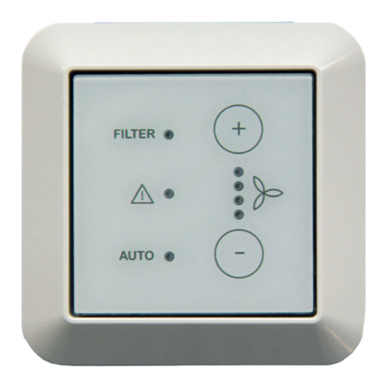
- Page 4 Bedieneinheit Verwendungszweck Aufbau / Lieferumfang Die Comfo LED (ComfoLED CH) bietet die Möglichkeit das Lüftungs- gerät bequem aus der Ferne zu bedienen. Das Bedienteil ist aus- schließlich für eine Unterputzin- stallation im Innenbereich in die marktüblichen Schalterprogramme geeignet und wird über ein maxi-...
-
Page 5: Elektrischer Anschluss
externe Bedieneinheit Funktionalität Elektrischer Anschluss Lüftungsgeräteseitig: Die Bedieneinheit verfügt über be- rührungssensitive Schaltflächen, Die Buchse der Mikrosteckverbin- das heißt, durch Berühren der be- dung des Anschlusskabels ist in treffenden Tasten werden die je- den Stecker der Mikrosteckverbin- weiligen Bedienfunktionen aus- dung BUS X7 der Steuerungspla- gelöst. - Page 6 externe Bedieneinheit ComfoSpot 50 Farb- Aderbelegung Farb- codie- Federzugklem- codie- rung rung Ziehen Sie das Steckverbindungs- Kabel Steck- schluss- bau- teil mit den Schraubklemmen ab und verbin- dien- kabel seits klemmen Sie die Adern des bausei- einheit tigen Kabels an. Notieren Sie die Rot (RT) Farbcodierung! Orange...
- Page 7 externe Bedieneinheit Stecken Sie nach Abnahme der PVC-Abdeckung der Steuerungs- platine die Buchse vorsichtig in den Stecker der Mikrosteckverbindung BUS X7 der Steuerungsplatine. Im Falle eines eingebauten RF-Mo- duls stecken Sie die Buchse in ei- nen der noch freien Stecker der zweifachen Mikrosteckverbindung.
-
Page 8: Intended Purpose
External control panel Intended purpose Design / Scope of delivery The Comfo LED (ComfoLED CH) allows the ventilation unit to be conveniently operated remote- ly. The control panel is only suit- able for indoor in-wall installation in conventional switch ranges and... -
Page 9: Electrical Connection
External control panel Functionality Electrical connection Ventilation unit side: The control panel has touch-sensi- tive buttons, which means the re- The socket of the connection ca- spective operating functions are ble’s micro connection must be in- triggered by touching the relevant serted into the plug of the BUS X7 buttons. - Page 10 External control panel ComfoSpot 50 Colour Wire assign- Colour coding of ment spring- coding the con- type terminals of the Disconnect the plug-in connector nection on-site Plug-in Con- cable cable part with the screw-type terminals connec- trol and connect the wires of the on- unit site cable.
- Page 11 External control panel After removing the PVC cover of the control board, carefully insert the socket into the plug of the con- trol board’s BUS X7 micro connec- tion. In case of a built-in RF module, in- sert the socket into one of the plugs of the dual micro connection that is still available.
-
Page 12: Utilisation Prévue
Interface de commande externe Utilisation prévue Structure / contenu de la livraison Le Comfo LED (ComfoLED CH) permet une commande aisée de l’appareil de ventilation à distance. L’interface de commande est exclu- sivement conçue pour une installa- tion encastrée en intérieur, dans les gammes d’interrupteurs courantes... -
Page 13: Raccordement Électrique
Interface de commande externe Fonctionnalité Raccordement électrique Côté appareil de ventilation : L’interface de commande dispose de surfaces tactiles, si bien qu’il suffit Le connecteur femelle du micro- d’effleurer les touches correspon- connecteur du câble de raccorde- dantes pour activer les fonctions ment doit être branché... - Page 14 Interface de commande externe ComfoSpot 50 Code Affectation des Code couleur conducteurs couleur Retirer la partie du connecteur câble de câble Con- Inter- raccor- fourni avec les bornes à vis et brancher necteur face dement par le les conducteurs du câble fourni par client com- le client.
- Page 15 Interface de commande externe Après avoir retiré le couvercle en PVC de la platine de commande, brancher avec précaution connecteur femelle sur le connec- teur mâle du microconnecteur BUS Dans le cas d’un module RF inté- X7 de la platine de commande. gré, brancher le connecteur femelle sur l’un des connecteurs encore libres du microconnecteur double.
-
Page 16: Impiego Previsto
Unità di comando esterna Impiego previsto Struttura / dotazione Comfo LED (ComfoLED CH) ester- na offre la possibilità di controllare comodamente a distanza il dispo- sitivo di ventilazione. Il pannello di comando è idoneo esclusivamen- te all’installazione incassata all’in- terno di gamme di interruttori comu-... -
Page 17: Collegamento Elettrico
Unità di comando esterna Funzionalità Collegamento elettrico Lato del dispositivo di ventilazione: L’unità di comando presenta super- fici di contatto sensibili al tatto, vale La presa del microconnettore del ca- a dire che toccando determinati pul- vo di collegamento deve essere in- serita nella spina del microconnetto- santi si attivano le rispettive funzioni di comando. - Page 18 Unità di comando esterna ComfoSpot 50 Codifica Assegnazione Codifi- dei colo- del filo ca dei Estrarre la parte del connettore con ri del cavo colori Con- Unità di collega- del ca- i morsetti a vite e fissare i fili del ca- net- di co- mento...
- Page 19 Unità di comando esterna Dopo aver rimosso il coperchio in PVC della scheda di comando, in- serire con cautela la presa nel con- nettore del microconnettore BUS X7 della scheda di comando. In caso di modulo RF integrato, in- serire la presa in uno dei connet- tori ancora liberi del microconnetto- re doppio.
- Page 20 Gebruiksdoel Opbouw / leveringsomvang Met de Comfo LED (ComfoLED CH) kan de ventilatie-unit comfor- tabel op afstand worden bediend. De bedieningsunit is uitsluitend geschikt voor inbouwinstallatie in binnentoepassingen in gangbare schakelaarprogramma's en wordt via een maximaal 25 m lange ka- ComfoLED bel met 4 aders (bijv.
-
Page 21: Elektrische Aansluiting
externe bedieningsunit Functionaliteit Elektrische aansluiting Ventilatie-unitzijde: De bedieningsunit beschikt over aanrakingsgevoelige schermknop- De bus van de microconnector van pen, wat inhoudt dat de diver- de aansluitkabel moet in de stek- se bedieningsfuncties door aanra- ker van de microconnector BUS X7 king van de bijbehorende knoppen van de besturingsprintplaat van de in gang worden gezet. - Page 22 externe bedieningsunit ComfoSpot 50 Kleurco- Draadtoewijzing Kleurco- dering dering van de kabel ter Con- Bestu- Trek het insteekverbindingsdeel aansluit- plaatse nec- ring- kabel met de schroefklemmen af en sluit seen- heid de aders van de ter plekke te leve- ren kabel aan. Noteer de kleurco- Rood dering! Oranje...
- Page 23 externe bedieningsunit Nadat u de PVC-afdekking van de besturingsprintplaat heeft verwij- derd, steekt u de bus voorzichtig in de connector van de microcon- nector BUS X7 van de besturings- printplaat. In geval van een ingebouwde RF- module steekt u de bus in een van de nog vrije stekkers van de dubbele microconnector.
- Page 24 ComfoLED wnętrzach, oraz jest połączony z centralą wentylacyjną 4-żyłowym kablem o długości maksymalnie 25 m (np. typu: J-Y(ST)Y 2x2x0,6). ComfoLED CH Zakres dostawy Poz. Nazwa Uwagi ComfoLED ComfoLED Składająca się z: przycisku dotykowego, Jednostka płyty montażowej z zaciskami śrubowymi...
-
Page 25: Zasilanie Elektryczne
Zewnętrzny panel sterowania Działanie Zasilanie elektryczne Po stronie centrali wentylacyjnej: Panel sterowania posiada dotyko- we przyciski, co oznacza, że do- Gniazdo mikrozłącza kabla przyłą- tknięcie dowolnego przycisku po- czeniowego należy podłączyć do woduje aktywację odpowiedniej wtyczki mikrozłącza BUS X7 płytki funkcji obsługowej. - Page 26 Zewnętrzny panel sterowania ComfoSpot 50 Oznaczenia Przyporządko- Oznacze- kolorystycz- wanie żył nia kolo- ne kabla rystycz- przyłącze- ne kabla Odłączyć element złącza wtykowe- Złącze Panel niowego zapew- wtyko- stero- nianego go z zaciskami śrubowymi i podłą- wania przez in- czyć żyły kabla w miejscu montażu. westora Zapisać...
- Page 27 Zewnętrzny panel sterowania Po zdjęciu osłony z PCV z płyt- ki sterującej ostrożnie podłączyć gniazdo do wtyczki mikrozłącza BUS X7 płytki sterującej. W przypadku wbudowanego modu- łu RF należy podłączyć gniazdo do jednej z wolnych wtyczek podwój- nego mikrozłącza. Ułożyć kabel przyłączeniowy w od- powiedniej rynience kablowej obu- dowy EPP i zasłonić...
- Page 28 Deutschland France The Netherlands Zehnder Group Deutschland Zehnder Group France Zehnder Group Nederland B.V. GmbH 3 rue du Bois Briard Lingenstraat 2 Almweg 34 91080 Courcouronnes 8028 PM Zwolle 77933 Lahr T +49 7821 586 0 T +33 169 361 646 T +31 38 42 96 911 F +49 7821 586 223 F +33 169 474 581...
Need help?
Do you have a question about the ComfoLED and is the answer not in the manual?
Questions and answers