
Subscribe to Our Youtube Channel
Related Manuals for Shakmat Harlequin's Context


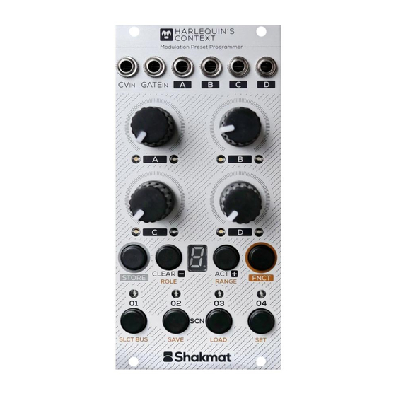
Summary of Contents for Shakmat Harlequin's Context
- Page 1 12HP Eurorack Module Built & designed in E.U. www.shakmat.com Shakmat Harlequin’s Context Building Guide...
-
Page 2: Table Of Contents
PCB stacking ......................... 12 Bottom PCB assembly ....................... 13 Front ..........................13 8.1.1 Push buttons & display ................13 Front panel preparation ..................... 14 LED mounting ........................15-16 Finish ............................17 First startup routine ......................18 Debug ............................19 • www.shakmat.com... -
Page 3: Preamble
1. Preamble Thank you for purchasing a Shakmat DIY kit ! We spare no effort in our kit packing process to prevent any mistakes or missing parts. In this document as well, we do our best to describe the assem- bly process in the most practical and comprehensive way. -
Page 4: Component List & Necessary Tools
2x 20 pin female header Necessay tools 1x 2x8 pin power header 4x 4 pin male header 4x WhiteLEDs Soldering iron 4x Green LEDs Solder 3x 22 µF electrolytic capacitors Cutting pliers 4x Metal potentiometers Masking tape 6x Jack connectors • www.shakmat.com 03/19... -
Page 5: Pcb Details
3. PCB details -12V Top PCB Front & back Bottom PCB Front & back • www.shakmat.com 04/19... - Page 6 Tactical Plan Front & back • www.shakmat.com 05/19...
-
Page 7: Top Pcb Assembly
Electrolytic capacitors (x3) Solder the three 22µF capacitors. You must pay attention to the orienta- tion of these components. The long leg indicates the positive side, therefore it has to match the + sign on the PCB silkscreen. • www.shakmat.com 06/19... -
Page 8: Back
Avoid touching the pins themselves because they will become hot very quickly and move out of alignment within their plastic bracket. Once you are satisfied with you placement, solder the remaining pins. • www.shakmat.com 07/19... -
Page 9: Power Header (2X8 Pin)
Check the alignment and correct with the same method as for a single row header. Then, once your component is upright and flat on the -12V PCB, solder the remaining pins. • www.shakmat.com 08/19... -
Page 10: Tactical Plan Assembly
Be VERY careful with the soldering of the female part of the headers. Once the potentiometers will be in place, those solder points will be inaccessible. After everything is well soldered, disconnect the Tactical Plan and proceed to the next step with the top PCB. • www.shakmat.com 09/19... -
Page 11: Top Pcb Final Assembly
If those jacks aren’t perpendicular, the front panel will be very hard to mount. If one of the jacks is not perfectly perpendicular with the PCB, you can reheat the pads and push it down with your thumb to re-align. • www.shakmat.com 10/19... -
Page 12: Potentiometers & Nuts
Mount the front panel and tighten the potentiometers nuts (this will ensure a proper placement of the pots) and then solder them. Once you have soldered everything, remove the nuts, the front panel and proceed to the next step. • www.shakmat.com 11/19... -
Page 13: Pcb Stacking
Repeat the same procedure as for the first point for all of the four points listed. Once they are all perfect, without any gap between the PCBs and headers, you can solder every remaining point. • www.shakmat.com 12/19... -
Page 14: Bottom Pcb Assembly
(holding the buttons in place with a piece of cardboard) and press it against a table. At the final step, if a button is not well aligned with the front panel, you can gently re-heat its solder points and push it into alignment. • www.shakmat.com 13/19... -
Page 15: Front Panel Preparation
You also need to screw the two nylon spacers on each of the two studs at the back of the front panel. Screw them until the end of the thread. These spacers will assure the stability & alignment of the PCB’s bottom half. • www.shakmat.com 14/19... -
Page 16: Led Mounting
PCB. For the bottom PCB, place the long leg in the upper hole. Place all the LEDs through the PCBs. Be aware of LED colors (some of their legs can be coloured to help you differenciate them). • www.shakmat.com 15/19... - Page 17 When all of its legs are soldered, it is imposible to correct its placement. Once it’s nicely placed, you can solder the remaining legs of the display and trim them. Potentiometer nuts (x4) Nylon screw (x2) • www.shakmat.com 16/19...
-
Page 18: Finish
You’re almost done! The last thing Button caps (x8) to do is to place the tactical plane on the top PCB. Pay attention to the orientation. The Shakmat logo must be on the left side as shown Jack nuts (x6) here. -
Page 19: First Startup Routine
Press the Store button to start the Factory Reset routine. This operation will clear all the non volatile memory, slot by slot, and the display will show the slot currently being cleared (from 1 to G). Once the Factory Reset routine is done, the module will start normally. • www.shakmat.com 18/19... -
Page 20: Debug
Check the buttons solder points. Check the PCB to PCB headers solder points on both PCBs. The 7 segment display is not working Check the display solder points. Check the PCB to PCB headers solder points on both PCBs. • www.shakmat.com 18/19... - Page 21 www.shakmat.com...
Need help?
Do you have a question about the Harlequin's Context and is the answer not in the manual?
Questions and answers