Table of Contents
Advertisement
Advertisement
Table of Contents

Subscribe to Our Youtube Channel
Related Manuals for Comica CVM-WM100 PLUS


Summary of Contents for Comica CVM-WM100 PLUS
- Page 1 CVM-WM100 PLUS UHF 1-Trigger-2 Wireless Microphone User Manual...
- Page 3 Technology Parameters Lavalier Transmitter TX Channels Group A Wireless Frequency 568.125MHz~579.875MHz Group B Wireless Frequency 580.125MHz~591.875MHz Transmitting Power 10dBm /15dBm Hand-held Transmitter HTX Channels Group A Wireless Frequency 568.125MHz~579.875MHz Group B Wireless Frequency 580.125MHz~591.875MHz Transmitting Power 10dBm /15dBm Receiver RX Channels Group A Wireless Frequency 568.125MHz~579.875MHz...
-
Page 4: Table Of Contents
Contents Foreword Main Features Notice Packing List Components and Instruction Lavalier Transmitter Hand-held Transmitter Receiver Button Instruction Indicator Light Instruction Installation and Usage Preparation Before Usage Transmitter Installation Receiver Installation Screen Display and Operation Lavalier Transmitter Hand-held Transmitter Receiver Specification... -
Page 5: Foreword
Foreword Thanks for purchasing COMICA WM100 PLUS wireless microphone. To ensure the smooth use and safety of the product, please carefully read this instruction before using and properly assemble and operate. Main Features . 1-Trigger-2, Perfectly Support Two Transmitters and One Receiver Work Simultaneously . -
Page 6: Packing List
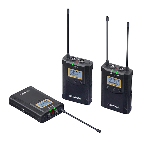
Packing List Main Parts: Lavalier Transmitter (TX) Hand-held Transmitter (HTX) Receiver (RX) Purchase Options: WM100 PLUS(A) = 2TX + RX WM100 PLUS(C) = TX + RX WM100 PLUS HTX:... - Page 7 Accessories: 3.5mm Mic Audio Input Cable USB Power Input Cable 3.5mm-3.5mm Audio Output Cable Portable Bag 3.5mm-XLR Audio Output Cable User Manual Belt Clip Certification Camera Mount Warranty Card Wind Muff The accessories of each combination include: WM100 PLUS(A) = X2 + X3 + X2 +...
-
Page 8: Components And Instruction
Components and Instruction Components Lavalier Transmitter (TX) Antenna Working Status Indicator On-off / Muting Button SET Function Menu Function Selection Button - LINE IN External Input IR Sensor Mic External Input IR Status Indicator Function Selection Button + Micro USB Port for External Power Supply Belt Clip 1/4 Thread Battery Tray... -
Page 9: Hand-Held Transmitter
Hand-held Transmitter (HTX) Microphone LCD Display Power / Muting Button IR Screen Low Cut Filter/Normal Audio Switch Signal Strength “High/Low” Switch High... -
Page 10: Receiver
Receiver (RX) Group A Antenna Group B Antenna Group A Working Status Indicator On-Off Button SET Function Button Function Selection Button - 3.5mm Audio Input Jack IR Sensor 3.5mm Monitoring Jack Group B Working Status Indicator Function Selection Button + Micro USB Port for External Power Supply Belt Clip 1/4 Thread... -
Page 11: Button Instruction
Function Button Instruction Long Press Power On / Off Lavalier Power / Muting Button Muting Mode Transmitter ( It is available only when Short Press / Receiver light up the screen) Enter the function Long Press SET Function Menu adjustment menu 1.Confirm the selected function Short Press... -
Page 12: Indicator Light Instruction
Low cut function: Cut the low frequency part and reduce the noise to make the sound more clear. Signal strength high/low switching effect: With high signal strength, the working distance is up to 60-100m, but high power consumption bring short battery life. With low signal strength, the working distance is up to 30-60m, but low power consumption bring long battery life. -
Page 13: Installation And Usage
Installation and Usage Preparation Before Usage (Transmitter Operating Steps same with Receiver) 1. Prepare Power Supply There're two ways of Power Supply, you can optionally choose AA batteries or External Power 1.1 Install two AA batteries into the battery tray according to their positive and negative electrode... - Page 14 1.2 External Power Supply Insert micro USB cable to the USB charging port to realize external power supply When it takes a long time to use, external mobile power supply can be used instead of AC-DC power supply, Micro USB otherwise noise will be introduced POWER...
- Page 15 1.3.Belt Clip Installation Please install the belt clip according to the illustration...
- Page 16 2. Hand-held Transmitter 2.1 Install two AA batteries into the battery tray according to the positive and negative electrode 2.2 Long press the button switch to turn on the hand-held transmitter 2.3 After the channel matched with the receiver, it can be used Please refer to screen operation instruction for channel matching.
-
Page 17: Transmitter Installation
3. Lavalier Transmitter Installation 3.1 Insert the 3.5mm audio input cable into MIC socket 3.2 Long press the power button to turn on the transmitter... - Page 18 3.3 Target the MIC to the audio source and check the working status according to the volume indicator on the screen Group A 570.875MHz Audio Dynamic Display Bar 3.4 After the channel matching with the receiver, it can be used Please refer to screen operation instruction for channel matching.
-
Page 19: Receiver Installation
4. Receiver Installation 4.1 Connect receiver to your video equipment through the camera mount 4.2 Connect the receiver to the camera or camcorder through the 3.5mm-3.5mm audio output cable, plug the headphone into the 3.5mm monitoring interface for real-time monitoring, then long press the power button to turn on the receiver Most DSLR cameras has 3. - Page 20 3.5mm Audio Output Monitoring Cable 3.5mm-3.5mm Audio Output Cable 3.5mm-XLR Audio Output Cable 4.3 After the channel matching with the receiver, it can be used Please refer to screen operation instruction for channel matching.
-
Page 21: Screen Display And Operation
Screen Display and Operation Instruction Lavalier Transmitter Screen Display Instruction Signal Strength High Group A Normal recording Muting(Unlocking) Signal Strength Low Group B Muting Muting(Locking) Power Indication Group A/B Group A 570.875MHz Channel Group A/B Audio dynamic display bar Channel Frequency... - Page 22 Operation Instruction 1.Manually Adjust the Channel of Transmitter 1.1 Long press button to CH setting display page Group A CH11 570.875MHz 1.2 Short press button to select the channel Group A 570.125MHz 1.3 Short press button to confirm Group A 570.125MHz...
- Page 23 2.Group A/B Selection 2.1 Press button to ‘ Group Setting ’ display page G r o u p S e t t i n g G r o u p A 2.2 Long press button to ‘ Group Setting ’ setting page G r o u p S e t t i n g G r o u p A 2.3 Press...
- Page 24 ‘ Low/High/OFF ’ Adjustment Low Cut Filter 3.1 Press button to ‘ Low Cut Filter ’ display page Low Cut Filter 3.2 Long press button to enter ‘ Low Cut Filter ’ setting page Low Cut Filter Low/High/OFF ’ 3.3 Press button to select LCF ‘...
- Page 25 4.Transmitting Signal Strength ‘ High/Low ’ Adjustment 4.1 Press button to ‘ RF Power ’ display page R F P o w e r H i g h 4.2 Long press button to ‘ RF Power ’ setting page R F P o w e r H i g h 4.3 Press button to adjust the transmitting signal strength...
- Page 26 5.Muting Mode Enable/ Disable 5.1 Press button to ‘ Muting ’ display page M u t i n g Enable 5.2 Long press button to ‘ Muting ’ setting page M u t i n g Enable 5.3 Press button to select Muting mode Enable/ Disable M u t i n g Disable 5.4 Short press...
- Page 27 When set to ‘ Disable ’, the muting control function cannot be used, the icon is: When set to ‘ Enable ’, the muting control function works, the icon is: The muting mode can be controlled only when the screen is on, press any button to light the screen and then press the button to switch the muting mode.
- Page 28 6.Backlight ‘ Lighting Time/Turn Off ’ Adjustment 6.1 Short Press button to ‘ Backlight ’ display page B a c k l i g h t 6.2 Long press button to ‘ Backlight ’ setting page B a c k l i g h t 6.3 Short press button to adjust the backlight lighting time or you can turn it off...
- Page 29 7. Reset to Defaults 7.1 Press button to ‘ Reset ’ display page R e s e t 7.2 Long press button to enter ‘ Reset ’ setting page R e s e t 7.3 Short press button to select whether to restore factory Settings R e s e t 7.4 Short press...
- Page 30 8. Version 8.1 Press button to ‘ Version ’ display page to check the version Ve r s i o n X.X.X...
-
Page 31: Hand-Held Transmitter
Hand-held Transmitter Muting mode Screen Display Instruction Normal recording mode Battery Level Channel Group A/B Operation Instruction 1.Turn on and Muting Mode Switch 1.1 Long press switch button for 2 seconds to turn on or off 1.2 When the transmitter turned on, short press the button to select muting mode Normal recording... - Page 32 2. Pair Through Infrared Sync 2.1 Set the channel through infrared sync Channel Channel The hand-held transmitter defaults to channel B, and you can set the group and channel through the receiver (For example, If Group A of the receiver is used for the matching, after matched, it will be: Group A CHXX;...
- Page 33 2.2 Function switch High Low cut adjustment switch RF-Low/ High...
-
Page 34: Receiver
Receiver Screen Display Instruction Group A Signal Strength Display Bar Group B Signal Strength Display Bar Power Indication Group A Group B Group A Group B CH 41 CH 11 Channel of Group A Channel of Group B Group A transmitting power Group B Transmitting power Group A Receiving Audio Status Indication Group B Receiving Audio Status Indication... - Page 35 Operation Instruction 1.Manually Adjust the Channel of Group A/ Group B 1.1 Long press button to 'CH' display page of Group A, and short press again to switch to 'CH' display page of Group B. Group A Group B CH 41 CH 11 1.2 Short press button to select the channel...
- Page 36 2.Audio Output Mode ‘Stereo/Mono’ Adjustment 2.1 Press button to ‘ Output Mode ’ display page Output Mode Stereo 2.2 Long press button to ‘ Output Mode ’ setting page Output Mode Stereo 2.3 Press button to select Mono/ Stereo Output Mode, Short press button to confirm Output Mode...
- Page 37 3.Group A/B Function Setting 3.1 Press button to ‘ Setting ’ display page Setting Group A 3.2 Long press button to ‘Group A / B Selection' Setting Page Setting Group A 3.3 Press button to select Group A/B Setting Group B 3.4 Short press button to confirm Setting...
- Page 38 4.Group A/B ‘ On/ Off ’ Adjustment Group A Setting 4.1 Short Press button to ‘ ’ display page Power ON Group A Setting Power ON 4.2 Long press button to ‘ Setting ’ setting page Group A Setting Power ON 4.3 Short Press button to select ‘...
- Page 39 5.Group A/B Volume Adjustment Group A Setting 5.1 Short Press button to ‘ ’ display page Volume Group A Setting Volume 12 5.2 Long press button to ‘ Volume ’ setting page Group A Setting Volume 12 5.3 Short Press button to adjust the volume Group A Setting Volume 8...
- Page 40 6. Group A/B Automatic Channel Scan 6.1 Short Press button to ‘ Auto Scan ’ display page Group A Setting Auto scan CH48 6.2 Long press button to enter ‘ Auto Scan ’ display page, and short press button to select whether to auto scan Group A Setting Auto scan ? 6.3 Short press...
- Page 41 7.Group A/B IR Sync Group A Setting 7.1 Short Press button to ‘ ’ display page Sync Group A Setting Sync 7.2 Long press button for IR Matching with transmitter Group A Setting Sync? 7.3 Use the button to select whether to match, and short press to confirm Group A Setting...
- Page 42 8. Backlight ‘ Lighting Time/Turn Off ’ Adjustment 8.1 Short Press button to ‘ Backlight ’ display page Backlight 8.2 Long press button to ‘ Backlight ’ setting page Backlight 8.3 Short press button to adjust the backlight lighting time or you can turn it off...
- Page 43 9. Reset to Defaults 9.1 Press button to ‘ Reset ’ display page Reset 9.2 Long press button to enter ‘ Reset ’ setting page Reset 9.3 Short press button to select whether to restore factory Settings Reset 9.4 Short press button to confirm and restore factory setting Reset Resetting..
- Page 44 10. Version 10.1 Press button to ‘ Version ’ display page to check the version Version X.X.X...
-
Page 45: Specification
Specification Lavalier Transmitter TX Duration 6 Hours Antenna 1/4 Wavelength Wire Antenna <-60dBc Stray Radiation <20ms Sound Delay <0.5% Audio Distortion >65dB Signal/Noise Frequency Response 20Hz~18KHz Audio Input Jack 3.5mm TRS Jack Battery AA Batteries×2pcs External Power Micro USB 5V/1A Dimension 107 x 66 x 26.1mm Operating Temperature... - Page 46 Hand-held Transmitter HTX Duration 6 Hours Antenna PCB Antenna Signal / Noise >65dB Stray Radiation <-60dBc Sound Delay <20ms Audio Distortion <0.5% Battery AA Batteries x 2pcs Φ53.5(MAX) x 253mm Dimension Operating Temperature 0℃ ~ 50℃ Storage Temperature -20℃ ~ 60℃...
- Page 47 Receiver RX Duration 6 Hours Antenna 1/4 Wavelength Wire Antenna Sensitivity -93dBm <20ms Sound Delay <0.5% Audio Distortion >65dB Signal/Noise Frequency Response 20Hz~18KHz Audio Input Jack 3.5mm TRS Jack Battery AA Batteries×2pcs External Power Micro USB 5V/1A Dimension 107 x 66 x 26.1mm Operating Temperature 0℃...
Need help?
Do you have a question about the CVM-WM100 PLUS and is the answer not in the manual?
Questions and answers
the receiver on my WM100 Plus shuts off if I have the mute activated on the transmitter for more than 30 seconds. Can I adjust this to allow for longer mute time without a shutdown?