Table of Contents
Advertisement
Quick Links
Advertisement
Chapters
Table of Contents

Subscribe to Our Youtube Channel
Related Manuals for RS PRO AFG-31000 Series


Summary of Contents for RS PRO AFG-31000 Series
- Page 1 Instruction Manual AFG-31000 Series Arbitrary Function Generator...
-
Page 3: Table Of Contents
Table of Contents Table of Contents SAFETY INSTRUCTIONS ................4 GETTING STARTED ..................11 Main Features ...................11 Panel Overview ..................13 Setting up the Function Generator ............19 QUICK REFERENCE ..................21 How to use the Digital Inputs ..............23 How to use the Help Menu ................ - Page 4 AFG-31000 Series Instruction Manual/English Frequency Sweep ................... 111 Burst Mode ..................... 123 SECONDARY SYSTEM FUNCTION SETTINGS ..........138 Save and Recall ..................139 Selecting the Remote Interface ..............143 System and Settings ................148 ARBITRARY WAVEFORMS ................156 Inserting Built-In Waveforms ..............158 Display an Arbitrary Waveform ..............
- Page 5 Save and Recall Commands ..............318 Error Messages ..................320 SCPI Status Registers ................336 APPENDIX ....................344 Fuse Replacement ................. 344 AFG-31000 Series Specifications ............345 EC Declaration of Conformity ..............355 INDEX ....................... 356 22/11/2016 Version No. 002...
-
Page 6: Safety Instructions
AFG-31000 Series Instruction Manual/English SAFETY INSTRUCTIONS This chapter contains important safety instructions that should be followed when operating and storing the function generator. Read the following before any operation to ensure your safety and to keep the function generator in the best condition. - Page 7 SAFETY INSTRUCTIONS Do not dispose electronic equipment as unsorted municipal waste. Please use a separate collection facility or contact the supplier from which this instrument was purchased. Safety Guidelines General Guideline Do not place heavy objects on the instrument. ...
- Page 8 AFG-31000 Series Instruction Manual/English (Measurement categories) EN 61010-1:2001 specifies the measurement categories and their requirements as follows. The AFG- 31000 falls under category II. Measurement category IV is for measurement performed at the source of a low-voltage installation. ...
- Page 9 SAFETY INSTRUCTIONS Cleaning the function Disconnect the power cord before cleaning the function generator. generator Use a soft cloth dampened in a solution of mild detergent and water. Do not spray any liquid into the function generator. Do not use chemicals containing harsh products such as benzene, toluene, xylene, and acetone.
- Page 10 AFG-31000 Series Instruction Manual/English Storage environment Location: Indoor Relative Humidity: < 70% Temperature: -10°C to 70°C Disposal Do not dispose this instrument as unsorted municipal waste. Please use a separate collection facility or contact the supplier from which this instrument was purchased.
- Page 11 SAFETY INSTRUCTIONS When using the function generator in the United Kingdom, make sure the power cord meets the following safety instructions. NOTE: This lead/appliance must only be wired by competent persons WARNING: THIS APPLIANCE MUST BE EARTHED IMPORTANT: The wires in this lead are coloured in accordance with the following code: Green/ Yellow: Earth Blue:...
- Page 12 AFG-31000 Series Instruction Manual/English Any exposed wiring from a cable, plug or connection that is engaged in a live socket is extremely hazardous. If a cable or plug is deemed hazardous, turn off the mains power and remove the cable, any fuses and fuse assemblies. All hazardous wiring must be immediately destroyed and replaced in accordance to the above standard.
-
Page 13: Getting Started
GETTING STARTED GETTING STARTED The Getting started chapter introduces the function generator’s main features, appearance, set up procedure and power-up. Main Features Model name Frequency bandwidth AFG-31081 80MHz AFG-31051 50MHz Performance DDS Function Generator series 1μHz high frequency resolution maintained at full range ... - Page 14 AFG-31000 Series Instruction Manual/English N Cycle and Infinite output mode selectable -60dBc low distortion sine wave Features Sine, Square, Ramp, Pulse, Noise, Sinc standard waveforms Internal and external LIN/LOG sweep with marker output Int/Ext AM, FM, PWM, FSK modulation ...
-
Page 15: Panel Overview
GETTING STARTED Panel Overview Front Panel LCD Display Number pad Scroll Selection Power Switch Wheel keys Output SYNC Terminals Output Waveform FREQ/Rate AMPL DC Offset UTIL Output key Sweep Burst Preset Function Operation Output USB port keys keys indicators LCD display TFT color LCD display, 480 x 272 resolution. - Page 16 AFG-31000 Series Instruction Manual/English The UTIL key is used to access the save and UTIL recall options, set the remote interface (USB, GPIB, RS232), use DSO link, update and view the firmware version, access the calibration options, output impedance settings, set the language and access the help menu.
- Page 17 GETTING STARTED USB host connector The USB Host connector is used to save and restore waveform data and images, as well as update the firmware. Output terminals Modulation output terminal. SYNC The SYNC output terminal. 50Ω output impedance. The primary output terminal. 50Ω output impedance.
- Page 18 AFG-31000 Series Instruction Manual/English Rear Panel Trigger Mark output Power socket and Power Switch Input fuse DISCONNECT POWER CORD AND TEST LEADS BEFORE REPLACING FUSE SER.NO. LABEL FUSE RATING AC 250V T 0.63A USB port RS232 INPUT OUTPUT Trigger MARK...
- Page 19 GETTING STARTED RS232 9 pin female RS232 socket used for PC remote control. RS232 port GPIB 24 pin female GPIB connector for PC remote GPIB control. Trigger Trigger output Trigger output terminal. MOD input Modulation input terminal. 22/11/2016 Version No. 002...
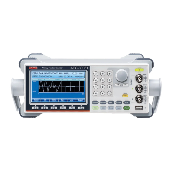
- Page 20 AFG-31000 Series Instruction Manual/English Display Parameter Windows Status Tabs Waveform Display Soft Menu Keys Parameter Windows The Parameter display and edit window. Status Tabs Shows the status of MOD, Sweep and Burst modes. Waveform Display The Waveform Display is used to output the waveform on the display.
-
Page 21: Setting Up The Function Generator
GETTING STARTED Setting up the Function Generator This section describes how adjust the handle and power up the Background function generator. Adjusting the stand Pull out the handle sideways SYNC and rotate it. Output Waveform FREQ/Rate AMPL DC Offset UTIL Sweep Burst Preset... - Page 22 AFG-31000 Series Instruction Manual/English Power Up 1. Connect the power cord to the socket on the rear panel. 2. Turn on the power switch on the rear panel. 3. Press and hold the Standby key on the front panel to turn the machine on.
-
Page 23: Quick Reference
QUICK REFERENCE QUICK REFERENCE This chapter lists operation shortcuts, built-in help coverage, and default factory settings. Use this chapter as a handy reference for instrument functions. This chapter is to be used as a quick reference, for detailed explanations on parameters, settings and limitations, please see the operation chapter (page 60) or specifications (page 345). - Page 24 AFG-31000 Series Instruction Manual/English ARB – Output Infinite Cycles ..............41 ARB – Output Markers ................42 Utility Menu ....................43 Save ...................... 43 Recall ....................43 Interface GPIB ..................43 Interface RS232 ..................44 Interface USB ..................44 Menu Tree ...................... 45 Waveform ....................
-
Page 25: How To Use The Digital Inputs
QUICK REFERENCE How to use the Digital Inputs Background The AFG-31000 has three main types of digital inputs: the number pad, selection keys and scroll wheel. The following instructions will show you how to use the digital inputs to edit parameters. 1. - Page 26 AFG-31000 Series Instruction Manual/English 4. Alternatively, the number pad can be used to set the value of a highlighted parameter. 22/11/2016 Version No. 002...
-
Page 27: How To Use The Help Menu
QUICK REFERENCE How to use the Help Menu Background Every key and function has a detailed description in the help menu. 1. Press UTIL. UTIL System 2. Press System (F5). Help 3. Press Help (F3). 4. Use the scroll wheel to navigate to a help item. - Page 28 AFG-31000 Series Instruction Manual/English Modulation Function Explains how to create Modulated waveforms. Sweep Function Provides help on the Sweep function. Burst Function Provides help on the Burst function. DSO Link Provides help on DSO link. Hardcopy Explains how to use the Hardcopy function.
- Page 29 QUICK REFERENCE 6. Use the scroll wheel to navigate to each help page. 7. Press F6 to return to the previous Return menus. 22/11/2016 Version No. 002...
-
Page 30: Selecting A Waveform
AFG-31000 Series Instruction Manual/English Selecting a Waveform Square Wave Example: Square Wave, 3Vpp, 75%Duty, 1 kHz Waveform Square 1. Press the Waveform key and select Square (F2). Output 2. Press Duty(F1), followed by 7 + 5 + Duty %(F5) Input: N/A 3. -
Page 31: Sine Wave
QUICK REFERENCE Input: N/A 2. Press the Freq/Rate key, followed FREQ/Rate by 1 + 0 + kHz (F5). 3. Press the AMPL key, followed by 5 AMPL +VPP (F6). 4. Press the output key. Output Sine Wave Example: Sine Wave, 10Vpp,100kHz Sine 1. -
Page 32: Modulation
AFG-31000 Series Instruction Manual/English Modulation Example: AM modulation. 100Hz modulating square wave. 1kHz Sine wave carrier. 80% modulation depth. 1. Press the MOD key and select AM (F1). Output Sine Waveform 2. Press Waveform and select Sine (F1). Input: N/A 3. - Page 33 QUICK REFERENCE Source 9. Press MOD, AM (F1), Source (F1), INT (F1). 10. Press the output key. Output Example: FM modulation. 100Hz modulating square wave. 1kHz Sine wave carrier. 100 Hz frequency deviation. Internal Source. 1. Press the MOD key and select FM (F2).
-
Page 34: Fsk Modulation
AFG-31000 Series Instruction Manual/English 8. Press 1 + 0 + 0 + Hz (F3). Source 9. Press MOD, FM (F2), Source (F1), INT (F1). 10. Press the output key. Output FSK Modulation Example: FSK modulation. 100Hz Hop frequency. 1kHz Carrier wave. Triangle wave. 10 Hz Rate. -
Page 35: Pwm Modulation
QUICK REFERENCE 7. Press 1 + 0 + 0 + Hz (F3). Source 8. Press MOD, FSK (F3), Source (F1), INT (F1). 9. Press the output key. Output PWM Modulation Example: PWM modulation. 800Hz Carrier wave. 15 kHz modulating sine wave. 50% Duty Cycle. - Page 36 AFG-31000 Series Instruction Manual/English 6. Press 1 + 5 + kHz (F3). Duty 7. Press MOD, PWM (F4), Duty (F2). 8. Press 5 + 0 + % (F1). Source 9. Press MOD, PWM (F4), Source (F1), INT (F1). 10. Press the output key.
-
Page 37: Sweep
QUICK REFERENCE Sweep Example: Frequency Sweep. Start Frequency 10mHz, Stop frequency 1MHz. Log sweep, 1 second sweep, Marker Frequency 550 Hz, Manual Trigger, Trigger out, rising edge. Start 1. Press Sweep, Start (F3). Sweep Output 2. Press 1 + 0 + mHz (F2). Stop 3. -
Page 38: Burst
AFG-31000 Series Instruction Manual/English 11. Press the output key. Output Source Manual Sweep 12. Press Sweep, Source (F1), Manual Trigger (F3), Trigger (F1). Burst Example: Burst Mode, N-Cycle (Internally triggered), 1kHz burst frequency, Burst count = 5, 10 ms Burst period, 0˚ burst phase, Internal trigger, 10 us delay, rising edge trigger out 1. - Page 39 QUICK REFERENCE N Cycle Trig Setup Burst 8. Press Burst, N Cycle (F1), TRIG Setup (F5), INT (F1). N Cycle Trig Setup 9. Press Burst, N Cycle (F1), TRIG Burst Delay Setup (F5), Delay (F4). 10. Press 1 + 0 + uSEC (F2). uSEC N Cycle TRIG setup...
-
Page 40: Arb
AFG-31000 Series Instruction Manual/English ARB – Add Built-In Waveform Example: ARB Mode, Exponential Rise. Start 0, Length 100, Scale 32767. Built in More 1. Press ARB, Built in (F3), More (F5), Exp Rise Exp Rise (F1). Output 2. Press Start (F1), 0 + Enter (F5),... -
Page 41: Arb - Add Point
QUICK REFERENCE 2. Press Freq.(F1),1, kHz (F5), Freq. Return (F6). Return 3. Press Duty (F2), 25, %(F5), Return Duty (F6). Return 4. Press Scale (F3), 32767, Enter Scale (F5), Return (F6), Done (F4). Enter Return Done ARB - Add Point Example: ARB Mode, Add point, Address 40, data 30,000. -
Page 42: Arb - Output Section
AFG-31000 Series Instruction Manual/English Edit Line Start ADD 1. Press ARB, Edit (F2), Line (F2), Start ADD (F1). Output 2. Press 1 + 0 + Enter (F5), Enter Return Return (F6). 3. Press Start Data (F2), 3 + 0, Start Data Enter (F5), Return (F6). -
Page 43: Arb - Output N Cycle
QUICK REFERENCE ARB – Output N Cycle Example: ARB Mode, Output N Cycle, Start 0, Length 1000, N Cycle 10. Output 1. Press ARB, Output (F6). Output 2. Press Start (F1), 0 + Enter (F5), Return Start Enter Return (F6). 3. -
Page 44: Arb - Output Markers
AFG-31000 Series Instruction Manual/English 3. Press Length (F2), 1 + 0 + 0, Length Enter (F5), Return (F6). Enter Return Return Infinite 4. Press Infinite (F5), Return (F6). ARB – Output Markers Example: ARB Mode, Output Markers, Start 0, Length 80. -
Page 45: Utility Menu
QUICK REFERENCE Utility Menu Save Example: Save to Memory file #5. Memory Store UTIL 1. Press UTIL, Memory (F1), Store (F1). 2. Choose a file using the scroll wheel Select Done and Select (F1), press Done (F5). Recall Example: Recall Memory file #5. Memory Recall 1. -
Page 46: Interface Rs232
AFG-31000 Series Instruction Manual/English 2. Press 1 + 0 + Done (F5). Done Interface RS232 Example: RS232 interface, Baud 115200, Parity None, Bits 8. RS232 Interface RS232 1. Press UTIL, Interface (F2), RS232 UTIL RS232 (F2). Baud Rate 115k 2. Press Baud Rate (F1), 115k (F5). -
Page 47: Menu Tree
QUICK REFERENCE Menu Tree Convention Use the menu trees as a handy reference for the function generator functions and properties. The AFG-31000 menu system is arranged in a hierarchical tree. Each hierarchical level can be navigated with the operation or soft menu keys. Pressing the Return soft key will return you to the previous menu level. -
Page 48: Waveform
AFG-31000 Series Instruction Manual/English Waveform Waveform Sine Square Triangle Pulse Ramp Noise Width Duty nSEC Return uSEC Return mSEC Return ARB-Display Display Horizon Vertical Next Page Back Page Overview Return Start Clear Clear Enter Enter Return Return Length High Clear... -
Page 49: Arb-Edit
QUICK REFERENCE ARB-Edit Edit Point Line Copy Clear Protect Return Address Start ADD Start Start Done Clear Clear Clear Clear Enter Enter Enter Enter Start Return Return Return Return Clear Data Start Data Length Length Enter Return Clear Clear Clear Clear Enter Enter... -
Page 50: Arb-Built In
AFG-31000 Series Instruction Manual/English ARB-Built in Built in Sine Square Ramp Sinc More Return Go to ARB Start Start Start Start Built in - Clear Clear Clear Clear Enter Enter Enter Enter More Return Return Return Return Length Length Length... -
Page 51: Arb- Built In- More
QUICK REFERENCE ARB- Built in- More Built in More Exp Rise Exp Fall Pulse Return Start Start Start Freq Clear Clear Clear Enter Enter Enter Return Return Return Length Length Length Clear Clear Clear Return Enter Enter Enter Duty Return Return Return Scale... -
Page 52: Arb-Save
AFG-31000 Series Instruction Manual/English ARB-Save Save Start Length Memory Return Clear Clear Select Select Enter Enter Return New Folder Return Return Enter Char Back Space Save Return New File Enter Char Back Space Save Return Return ARB-Load Load Memory Done... -
Page 53: Arb-Output
QUICK REFERENCE ARB-Output Output Start Length Marker N Cycle Infinite Return Clear Clear Start Cycles Enter Enter Clear Clear Enter Enter Return Return Return Return Length Trigger Return Clear Enter Return Return 22/11/2016 Version No. 002... -
Page 54: Mod
AFG-31000 Series Instruction Manual/English Source Source Source Source Return Return Return Return Depth Freq Dev Hop Freq Duty Return Return AM Freq PWM Freq Return Return FM Freq FSK Rate Return Return Shape Shape Sine Sine Square Square Return Triangle... -
Page 55: Sweep
QUICK REFERENCE Sweep SWEEP Source Type Start Stop SWP Time More Linear mSEC Go to the Sweep - Return Return More menu Manual Trigger Return Return Return Return Sweep - More Sweep More Span Center Marker TRIG out Return Rise Freq Fall ON/OFF... -
Page 56: Burst - N Cycle
AFG-31000 Series Instruction Manual/English Burst – N Cycle Burst N Cycle Cycles Infinite Phase Period TRIG Setup Return Clear Clear uSEC Degree mSEC Return Return Rise Return Fall Return Manual Trigger Return Delay nSEC uSEC mSEC Return TRIG out Rise... -
Page 57: Burst - Gate
QUICK REFERENCE Burst - Gate Burst Gate Polarity Phase Return Clear Degree Return Return UTIL UTIL Memory Interface Cal. Load System DSO-Link Go to the Search Store Self Test 50 OHM Hardcopy UTIL – High Z Select Software Language Done Interface Return 中文... -
Page 58: Util - Interface
AFG-31000 Series Instruction Manual/English UTIL - Interface UTIL Interface GPIB RS-232 Return Address Baud Rate Clear 9600 Done 19.2K Return 38.4K 57.6K Return 115K Return Parity/Bits None/8Bits Odd/7Bits Even/7Bits Return Return 22/11/2016 Version No. 002... -
Page 59: Default Settings
QUICK REFERENCE Default Settings Here are the default panel settings which appear when pressing the Preset Preset key. Output Config. Function Sine wave Frequency 1kHz Amplitude 3.000 Vpp Offset 0.00V dc Output units 50Ω Output terminal Modulation (AM/FM/FSK) Carrier Wave 1kHz Sine wave Modulation waveforms 100Hz Sine wave... - Page 60 AFG-31000 Series Instruction Manual/English Sweep Start/Stop frequency 100Hz/1kHz Sweep time Sweep type Linear Sweep status Burst Burst Frequency 1kHz Ncycle Burst period 10ms 0˚ Burst starting phase Burst status System settings Power off signal Display mode Error queue cleared Memory settings...
- Page 61 QUICK REFERENCE Interface RS232 Baud rate 115200 Parity None (8 data bits) Calibration Calibration Menu Restricted 22/11/2016 Version No. 002...
-
Page 62: Operation
AFG-31000 Series Instruction Manual/English OPERATION The Operation chapter shows how to output basic waveform functions. For details on modulation, sweep, burst and arbitrary waveforms, please see the Modulation and Arbitrary waveform chapters on pages 70 and 156. Select a Waveform ..................61 Sine Wave ..................... -
Page 63: Select A Waveform
OPERATION Select a Waveform The AFG-31000 can output six standard waveforms: sine, square, triangle, pulse, ramp and noise waveforms. Sine Wave Panel Operation 1. Press the Waveform key. Waveform Sine 2. Press F1 (Sine). 22/11/2016 Version No. 002... -
Page 64: Setting A Square Wave
AFG-31000 Series Instruction Manual/English Setting a Square Wave Panel Operation 1. Press the Waveform key. Waveform Square 2. Press F2 (Square) to create a square waveform. DUTY 3. Press F1 (Duty). The Duty parameter will be highlighted in the parameter window. -
Page 65: Triangle Wave
OPERATION Triangle Wave Panel Operation 1. Press the Waveform key. Waveform 2. Press F3 (Triangle). Triangle Setting the Pulse Width Panel Operation 1. Press the Waveform key. Waveform 22/11/2016 Version No. 002... - Page 66 AFG-31000 Series Instruction Manual/English Pulse 2. Press F4 (Pulse) to create a pulse waveform. Width 3. Press F1 (Width). The Width parameter will be highlighted in the parameter window. 4. Use the selector keys and scroll wheel or number pad to enter the pulse width.
-
Page 67: Setting A Ramp
OPERATION Setting a Ramp Panel Operation 1. Press the Waveform key. Waveform Ramp 2. Press F5 (Ramp) to create a ramp waveform. 3. Press F1 (SYM). The SYMM parameter will be highlighted in the parameter window. 4. Use the selector keys and scroll wheel or number pad to enter the symmetry percentage. -
Page 68: Setting The Frequency
AFG-31000 Series Instruction Manual/English Panel Operation 1. Press the Waveform key. Waveform Noise 2. Press F6 (Noise). Setting the Frequency Panel Operation 1. Press the FREQ/Rate key. FREQ/Rate 2. The FREQ parameter will become highlighted in the parameter window. 3. Use the selector keys and scroll wheel or number pad to enter the frequency. - Page 69 OPERATION 4. Choose a frequency unit by pressing F2~F6. Range Sine 1μHz~80MHz(31081)/50MHz(31051) Square 1μHz~80MHz(31081)/50MHz(31051) Triangle 1μHz~1MHz Pulse 500μHz~50MHz Ramp 1μHz~1MHz 22/11/2016 Version No. 002...
-
Page 70: Setting The Amplitude
AFG-31000 Series Instruction Manual/English Setting the Amplitude Panel Operation 1. Press the AMPL key. AMPL 2. The AMPL parameter will become highlighted in the parameter window. 3. Use the selector keys and scroll wheel or number pad to enter the amplitude. -
Page 71: Setting The Dc Offset
OPERATION Setting the DC Offset Panel Operation 1. Press the DC Offset key. DC Offset 2. The DC Offset parameter will become highlighted in the parameter window. 3. Use the selector keys and scroll wheel or number pad to enter the DC Offset. mVDC 4. -
Page 72: Modulation
AFG-31000 Series Instruction Manual/English MODULATION The AFG-31000 Series Arbitrary Function Generators are able to produce AM, FM, FSK and PWM modulated waveforms. Depending on the type of waveform produced, different modulation parameters can be set. Only one modulation mode can be active at any one time. - Page 73 MODULATION FSK Carrier Frequency ................. 97 FSK Hop Frequency................99 FSK Rate.................... 100 FSK Source ..................101 Pulse Width Modulation ................. 103 Selecting Pulse Width Modulation ............104 PWM Carrier Shape ................104 PWM Carrier Frequency ..............105 PWM Modulating Wave Shape ............105 Modulating Waveform Frequency ............
- Page 74 AFG-31000 Series Instruction Manual/English Burst Period ..................129 Burst Phase ..................131 Burst Trigger Source ................132 Burst Delay ..................134 Burst Trigger Output ................136 22/11/2016 Version No. 002...
-
Page 75: Amplitude Modulation (Am)
MODULATION Amplitude Modulation (AM) An AM waveform is produced from a carrier waveform and a modulating waveform. The amplitude of the modulated carrier waveform depends on the amplitude of the modulating waveform. The AFG-31000 function generator can set the carrier frequency, amplitude and offset as well as internal or external modulation sources. -
Page 76: Selecting Am Modulation
AFG-31000 Series Instruction Manual/English Selecting AM Modulation Panel Operation 1. Press the MOD key. 2. Press F1 (AM). AM Carrier Shape Background The shape function selects the AM carrier waveform shape. Sine, square, triangle, ramp, pulse or arbitrary waveforms can be used as the carrier shape. -
Page 77: Carrier Frequency
MODULATION Sine Ramp 2. Press F1~F5 to choose the carrier wave shape. Select an Arbitrary 3. See the Arbitrary waveform quick guide Page 38 , Page 156 Waveform Carrier or chapter to use an arbitrary waveform. Shape. Range AM Carrier Shape sine, square, triangle, upramp, dnramp, arbitrary waveform Carrier Frequency... - Page 78 AFG-31000 Series Instruction Manual/English Range Carrier Shape Carrier Frequency Sine 1μHz~80MHz(31081)/ 50MHz(31051) Square 1μHz~80MHz(31081)/ 50MHz(31051) Triangle 1μHz~1MHz Pulse 500μHz~50MHz Ramp 1μHz~1MHz 22/11/2016 Version No. 002...
-
Page 79: Modulating Wave Shape
MODULATION Modulating Wave Shape The function generator can accept internal as well as external sources. The AFG-31000 has sine, square, triangle, up ramp and down ramp modulating waveform shapes. Sine waves are the default wave shape. Panel Operation 1. Select MOD. 2. - Page 80 AFG-31000 Series Instruction Manual/English 22/11/2016 Version No. 002...
-
Page 81: Am Frequency
MODULATION AM Frequency The frequency of the modulation waveform (AM Frequency) can be set from 2mHz to 20kHz. Panel Operation 1. Press the MOD key. 2. Press F1 (AM). AM Freq 3. Press F3 (AM Freq). 4. The AM Freq parameter will become highlighted in the Waveform display area. - Page 82 AFG-31000 Series Instruction Manual/English Range Modulation frequency 2mHz~20kHz Default frequency 100Hz 22/11/2016 Version No. 002...
-
Page 83: Modulation Depth
MODULATION Modulation Depth Modulation depth is the ratio (as a percentage) of the unmodulated carrier amplitude and the minimum amplitude deviation of the modulated waveform. In other words, modulation depth is the maximum amplitude of the modulated waveform compared to the carrier waveform as a percentage. -
Page 84: Selecting (Am) Modulation Source
AFG-31000 Series Instruction Manual/English 5. Use the selector keys and scroll wheel or number pad to enter the AM depth. 6. Press F1 (%) to choose % units. Range Depth 0%~120% Default depth 100% Note When the modulation depth is greater than 100%, the output cannot exceed ±5VPeak (10kΩ... - Page 85 MODULATION 4. To select the source, press F1 (Internal) or F2 (External). Return 5. Press F6 (Return) to return to the menu. ±5V External Source Use the MOD INPUT terminal on the rear panel when using an external source. Note If an external modulation source is selected, modulation depth is limited to ±...
-
Page 86: Frequency Modulation (Fm)
AFG-31000 Series Instruction Manual/English Frequency Modulation (FM) A FM waveform is produced from a carrier waveform and a modulating waveform. The instantaneous frequency of the carrier waveform varies with the magnitude of the modulating waveform. When using the AFG-31000 function generator, only one type of modulated waveform can be created at any one time. -
Page 87: Selecting Frequency Modulation (Fm)
MODULATION Selecting Frequency Modulation (FM) When FM is selected, the modulated waveform depends on the carrier frequency, the output amplitude and offset voltage. Panel Operation 1. Press the MOD key. 2. Press F2 (FM). FM Carrier Shape Background The Shape mode selects the FM carrier waveform shape. The default waveform shape is set to sine. -
Page 88: Fm Carrier Frequency
AFG-31000 Series Instruction Manual/English Sine Ramp 2. Press F1~F5 to choose the carrier wave shape. (bar F4) Range Carrier Shape Sine, Square, Triangle, Ramp. FM Carrier Frequency When using the AFG-31000 function generator, the carrier frequency must be equal to or greater than the frequency deviation. -
Page 89: Fm Wave Shape
MODULATION Sine 1μHz~80MHz(31081)/ 50MHz(31051) Square 1μHz~80MHz(31081)/ 50MHz(31051) Triangle 1μHz~1MHz Ramp 1μHz~1MHz Default frequency 1 kHz FM Wave Shape The function generator can accept internal as well as external sources. The AFG-31000 has sine, square, triangle, positive and negative ramps (UpRamp, DnRamp) as the internal modulating waveform shapes. - Page 90 AFG-31000 Series Instruction Manual/English Triangle 50% Symmetry DnRamp 0% Symmetry 22/11/2016 Version No. 002...
-
Page 91: Frequency Modulation Waveform
MODULATION Frequency Modulation Waveform For frequency modulation, the function generator will accept internal or external sources. Panel Operation 1. Press the MOD key. 2. Press F2 (FM). FM Freq 3. Press F3 (FM Freq). 4. The FM Freq parameter will become highlighted in waveform display panel. - Page 92 AFG-31000 Series Instruction Manual/English Range Modulation frequency 2mHz~20kHz Default frequency 100Hz 22/11/2016 Version No. 002...
-
Page 93: Frequency Deviation
MODULATION Frequency Deviation The frequency deviation is the peak frequency deviation from the carrier wave and the modulated wave. Panel Operation 1. Press the MOD key. 2. Press F2 (FM). Freq Dev 3. Press F2 (Freq Dev). 4. The Freq Dev parameter will become highlighted in the waveform display panel. -
Page 94: Selecting (Fm) Modulation Source
AFG-31000 Series Instruction Manual/English 6. Press F1~ F5 to choose the frequency units. DC~80MHz (31081) DC~50MHz Range Frequency Deviation (31051) DC~1MHz (Triangle) Default depth 100kHz Selecting (FM) Modulation Source The function generator will accept an internal or external source for FM modulation. The default source is internal. - Page 95 MODULATION Note If an external modulating source is selected, the frequency deviation is limited to the ± 5V MOD INPUT terminal on the rear panel. The frequency deviation is proportional to the signal level of the modulation in voltage. For example, if the modulation in voltage is +5V, then the frequency deviation would be equal to the set frequency deviation.
-
Page 96: Frequency Shift Keying (Fsk) Modulation
AFG-31000 Series Instruction Manual/English Frequency Shift Keying (FSK) Modulation Frequency Shift Keying Modulation is used to shift the frequency output of the function generator between two preset frequencies (carrier frequency, hop frequency). The frequency at which the carrier and hop frequency shift is determined by the internal rate generator or the voltage level from the Trigger INPUT terminal on the rear panel. -
Page 97: Selecting Fsk Modulation
MODULATION Selecting FSK Modulation When using FSK mode, the output waveform uses the default settings for carrier frequency, amplitude and offset voltage. Panel Operation 1. Press the MOD key. 2. Press F3 (FSK). FSK Carrier Shape Background The shape function selects the FSK carrier waveform shape. The default waveform shape is set to sine. - Page 98 AFG-31000 Series Instruction Manual/English Sine Ramp 2. Press F1~F5 to choose the carrier wave shape. (bar F4) Range Carrier Shape Sine, Square, Triangle, Ramp, Pulse 22/11/2016 Version No. 002...
-
Page 99: Fsk Carrier Frequency
MODULATION FSK Carrier Frequency The maximum carrier frequency depends on the carrier shape. The default carrier frequency for all carrier shapes is 1kHz. The voltage level of the Trigger INPUT signal controls the output frequency when EXT is selected. When the Trigger INPUT signal is logically low the carrier frequency is output and when the signal is logically high, the hop frequency is output. - Page 100 AFG-31000 Series Instruction Manual/English Ramp 1μHz~1MHz Pulse 500μHz~50MHz 22/11/2016 Version No. 002...
-
Page 101: Fsk Hop Frequency
MODULATION FSK Hop Frequency The default Hop frequency for all waveform shapes is 100 Hz. A square wave with a duty cycle of 50% is used for the internal modulation waveform. The voltage level of the Trigger INPUT signal controls the output frequency when EXT is selected. When the Trigger INPUT signal is logically low the carrier frequency is output and when the signal is logically high, the hop frequency is output. -
Page 102: Fsk Rate
AFG-31000 Series Instruction Manual/English 5. Use the selector keys and scroll wheel or number pad to enter the hop frequency. 6. Press F1~F5 to select the frequency range. Range Waveform Carrier Frequency Sine 1μHz~80MHz(31081)/ 50MHz(31051) Square 1μHz~80MHz(31081)/ 50MHz(31051) Triangle 1μHz~1MHz Ramp 1μHz~1MHz... -
Page 103: Fsk Source
MODULATION 3. Press F3 (FSK Rate). FSK Rate 4. The FSK Rate parameter will become highlighted in the waveform display area. 5. Use the selector keys and scroll wheel or number pad to enter the FSK rate. 6. Press F1~F5 to select the frequency unit. - Page 104 AFG-31000 Series Instruction Manual/English Rate function. When an external source is selected the FSK rate is equal to the frequency of the Trigger INPUT signal on the rear panel. Panel Operation 1. Press the MOD key. 2. Press F3 (FSK).
-
Page 105: Pulse Width Modulation
MODULATION Pulse Width Modulation For pulse width modulation the instantaneous voltage of the modulating waveform determines the width of the pulse waveform. Only one mode of modulation can be enabled at any one time. If PWM is enabled, any other modulation mode will be disabled. Likewise, burst and sweep modes cannot be used with PWM and will be disabled when PWM is enabled. -
Page 106: Selecting Pulse Width Modulation
AFG-31000 Series Instruction Manual/English Selecting Pulse Width Modulation When selecting PWM, the current setting of the carrier frequency, the amplitude modulation frequency, output, and offset voltage must be considered. Panel Operation 1. Press the MOD key. Waveform Square 2. Press F2 (Square). -
Page 107: Pwm Carrier Frequency
MODULATION PWM Carrier Frequency The carrier frequency depends on the square wave. The default carrier frequency is 1kHz. Panel Operation 1. To select the carrier frequency, press FREQ/Rate the FREQ/ Rate key. 2. The FREQ parameter will become highlighted in the parameter window. -
Page 108: Modulating Waveform Frequency
AFG-31000 Series Instruction Manual/English Shape 3. Press F4 (Shape). Sine DnRamp 4. Press F1~F5 to select a waveform shape. 5. Press F6 (Return) to return to the menu. Return Range Waveform Square 50% Duty cycle UpRamp 100% Symmetry Triangle 50% Symmetry... -
Page 109: Modulation Duty Cycle
MODULATION 3. Press F3 (PWM Frequency). PWM Freq 4. The PWM Freq parameter will become highlighted in the Waveform Display area. 5. Use the selector keys and scroll wheel or number pad to enter the PWM frequency. 6. Press F1~F3 to select the frequency unit range. - Page 110 AFG-31000 Series Instruction Manual/English 2. Press F4 (PWM). Duty 3. Press F2 (Duty). 4. The Duty parameter will become highlighted in the waveform display area. 5. Use the selector keys and scroll wheel or number pad to enter the Duty cycle.
-
Page 111: Pwm Source
MODULATION PWM Source The AFG-31000 accepts internal and external PWM sources. Internal is the default source for PWM sources. Panel Operation 1. Press the MOD key. 2. Press F4 (PWM). Source 3. Press F1 (Source). 4. To select the source, press F1 (Internal) or F2 (External). - Page 112 AFG-31000 Series Instruction Manual/English 22/11/2016 Version No. 002...
-
Page 113: Frequency Sweep
MODULATION Frequency Sweep The function generator can perform a sweep for sine, square or ramp waveforms, but not noise, and pulse. When Sweep mode is enabled, Burst or any other modulation modes will be disabled. When sweep is enabled, burst mode is automatically disabled. In Sweep mode the function generator will sweep from a start frequency to a stop frequency over a number of designated steps. -
Page 114: Selecting Sweep Mode
AFG-31000 Series Instruction Manual/English Selecting Sweep Mode The Sweep button is used to output a sweep. If no settings have Sweep been configured, the default settings for output amplitude, offset and frequency are used. Setting Start and Stop Frequency The start and stop frequencies define the upper and lower sweep limits. The function generator will sweep from the start through to the stop frequency and cycle back to the start frequency. - Page 115 MODULATION 4. Use the selector keys and scroll wheel or number pad to enter the Stop/Start frequency. 5. Press F1~F5 to select the Start/Stop frequency units. Range Sweep Range 100μHz~80MHz(31081) 100μHz~50MHz(31051) (Sine/Square) 100μHz~1MHz (Triangle) Start - Default 100Hz Stop - Default 1kHz To sweep from low to high frequencies, set the start frequency less Note...
-
Page 116: Center Frequency And Span
AFG-31000 Series Instruction Manual/English Center Frequency and Span A center frequency and span can be set to determine the upper and lower sweep limits (start/stop). Panel Operation 1. Press the SWEEP key. Sweep More 2. Press F6 (More). Span Center 3. - Page 117 MODULATION Range Center Frequencies 100μHz~80MHz(31081) 100μHz~50MHz(31051) (Sine/Square) 100μHz~1MHz (Triangle) Span Frequency DC~80MHz(31081) DC~50MHz(31051) (Sine/Square) DC ~1MHz (Triangle) Center - Default 550Hz Span – Default 900Hz Note To sweep from low to high frequencies, set a positive span. To sweep from high to low frequencies, set a negative span. When marker is off, the SYNC signal is a square wave with a duty cycle of 50%.
-
Page 118: Sweep Mode
AFG-31000 Series Instruction Manual/English Sweep Mode Sweep mode is used to select between linear or logarithmic sweeping. Linear sweeping is the default setting. Panel Operation 1. Press the SWEEP key. Sweep Type 2. Press F2 (Type). Linear 3. To select linear or logarithmic sweep, press F1 (Linear) or F2 (Log). -
Page 119: Sweep Time
MODULATION Sweep Time The sweep time is used to determine how long it takes to perform a sweep from the start to stop frequencies. The function generator automatically determines the number of discrete frequencies used in the scan depending on the length of the scan. Panel Operation 1. - Page 120 AFG-31000 Series Instruction Manual/English Range Sweep time 1ms ~ 500s Default 22/11/2016 Version No. 002...
-
Page 121: Marker Frequency
MODULATION Marker Frequency The marker frequency is the frequency at which the marker signal goes low (The marker signal is high at the start of each sweep). The marker signal is output from the MARK terminal on the rear panel. The default is 550 Hz. Panel Operation 1. -
Page 122: Sweep Trigger Source
AFG-31000 Series Instruction Manual/English 7. Use the selector keys and scroll wheel or number pad to enter the frequency. 8. Press F1~F5 to select the frequency unit. Range Frequency 100μHz~80MHz(31081) 100μHz~50MHz(31051) 100μHz~1MHz (Ramp) Default 550Hz Note The marker frequency must be set to a value between the start and stop frequencies. -
Page 123: Trigger Output
MODULATION Source 2. Press F1 (Source). Manual 3. To select the source, press F1 (Internal), F2 (External) or F3 (Manual). 4. Press F6 (Return) to return to the menu. Return Note Using the Internal source will produce a continuous sweep using the sweep time settings. - Page 124 AFG-31000 Series Instruction Manual/English the beginning of a sweep. The signal can also be set to falling edge. Panel Operation 1. Press the SWEEP key. Sweep More 2. Press F6 (More). TRIG out 3. Press F4 (TRIG out). ON/OFF 4. Press F3 (ON/OFF).
-
Page 125: Burst Mode
MODULATION Burst Mode The function generator can create a waveform burst with a designated number of cycles. Burst mode supports sine, square, triangle and ramp waveforms. Burst 22/11/2016 Version No. 002... -
Page 126: Selecting Burst Mode
AFG-31000 Series Instruction Manual/English Selecting Burst Mode When burst mode is selected, any modulation or sweep modes will Burst be automatically disabled. If no settings have been configured, the default settings for output amplitude, offset and frequency are used. Burst Modes Burst mode can be configured using Triggered (N Cycle mode) or Gated mode. -
Page 127: Burst Frequency
MODULATION In Gated mode, burst count, burst cycle and trigger source are ignored. If a trigger is input, then the trigger will be ignored and will not generate any errors. Panel Operation 1. Press the Burst key. Burst N Cycle Gate 2. -
Page 128: Burst Cycle/Burst Count
AFG-31000 Series Instruction Manual/English 4. Press F2~F6 to choose the frequency unit. 2mHz~80MHz(31081)/ Range Frequency 50MHz(31051) Frequency – Ramp 2mHz~1MHz Default 1kHz Note Waveform frequency and burst period are not the same. The burst period is the time between the bursts in N-Cycle mode. - Page 129 MODULATION 5. Use the selector keys and scroll wheel or number pad to enter the number of cycles. 6. Press F5 to select the Cyc unit. Range Cycles 1~1,000,000 22/11/2016 Version No. 002...
-
Page 130: Infinite Burst Count
AFG-31000 Series Instruction Manual/English Note Burst cycles are continuously output when the internal trigger is selected. The burst period determines the rate of bursts and the time between bursts. Burst cycle must be less than the product of the burst period and wave frequency. - Page 131 MODULATION Above 25MHz, Infinite burst is only available with square and sine waveforms. Burst Period The burst period is used to determine the time between the start of one burst and the start of the next burst. It is only used for internally triggered bursts. Panel Operation 1.
- Page 132 AFG-31000 Series Instruction Manual/English 5. Use the selector keys and scroll wheel or number pad to enter period time. uSEC 6. Press F1~F3 to choose the period time unit. Range Period time 1ms~500s Default 10ms Note Burst period is only applicable for internal triggers. Burst period settings are ignored when using gated burst mode or for external and manual triggers.
- Page 133 MODULATION Burst Phase Burst Phase defines the starting phase of the burst waveform. The default is 0˚. Panel Operation 1. Press the Burst key. Burst N Cycle 2. Press F1 (N Cycle). Phase 3. Press F3 (Phase). 4. The Phase parameter will become highlighted in the Waveform Display area.
- Page 134 AFG-31000 Series Instruction Manual/English Range Phase -360˚~+360˚ 0˚ Default When using sine, square, triangle or ramp waveforms, 0˚ is the point Note where the waveforms are at zero volts. 0˚ is the starting point of a waveform. For sine, square or Triangle, Ramp waveforms, 0˚...
- Page 135 MODULATION Manual 4. Choose a trigger type by pressing F1 (INT), F2 (EXT) or F3 (Manual). Manual Triggering If a manual source is selected, the trigger softkey (F1) must be pressed each time to output a burst. Note When the internal trigger source is chosen, the burst is output continuously at a rate defined by the burst period setting.
- Page 136 AFG-31000 Series Instruction Manual/English A time delay can be inserted after each trigger, before the start of a burst. Burst Delay Panel Operation 1. Press the Burst key. Burst N Cycle 2. Press F1 (N Cycle). TRIG setup 3. Press F5 (TRIG setup).
- Page 137 MODULATION nSEC 7. Press F1~F4 to choose the delay time unit. Range Delay time 0s~80s Default 22/11/2016 Version No. 002...
- Page 138 AFG-31000 Series Instruction Manual/English Burst Trigger Output The Trig Out terminal on the rear panel can be used for burst or sweep modes to output a TTL compatible trigger signal. By default the trigger signal is rising edge. The trigger signal is output at the start of each burst.
- Page 139 MODULATION 22/11/2016 Version No. 002...
-
Page 140: Secondary System Function Settings
AFG-31000 Series Instruction Manual/English SECONDARY SYSTEM FUNCTION SETTINGS The secondary system functions are used to store and recall settings, set the RS232/USB/GPIB settings, view the software version, update the firmware, perform self calibration, set the output impedance, change the language and configure DSO link. -
Page 141: Save And Recall
SECONDARY SYSTEM FUNCTION SETTINGS Save and Recall The AFG-31000 has non-volatile memory to store instrument state and ARB data. There are 10 memory files numbered 0~9. Each memory file can either store arbitrary waveform data (ARB), settings or both. When data (ARB or Setting data) is stored in a memory file, the data will be shown in red. - Page 142 AFG-31000 Series Instruction Manual/English Impedance Source Main output Shape Sweep Rate Source Hop frequency Type Trigger out Source Marker Shape Time Duty ...
- Page 143 SECONDARY SYSTEM FUNCTION SETTINGS Store 3. Choose a file operation: Recall Press F1 to store a file, press F2 to Delete recall a file, or press F3 to delete a file. 4. Use the scroll wheel to highlight a memory file. Press F1 (Select) to choose the file.
- Page 144 AFG-31000 Series Instruction Manual/English Range Memory file Memory0 ~ Memory9 Data type ARB, Setting, ARB+Setting Done 6. Press F5 (Done) to confirm the operation. Delete All Delete All 7. To delete all the files for Memory0~Memory9, press F4. Done 8. Press F1 (Done) to confirm the deletion of all files.
-
Page 145: Selecting The Remote Interface
SECONDARY SYSTEM FUNCTION SETTINGS Selecting the Remote Interface The AFG-31000 has RS232, GPIB and USB interfaces for remote control. Only one remote interface can be used at any one time. GPIB Interface Background When using the GPIB interface, a GPIB address must be specified. The default GPIB interface is 10. -
Page 146: Rs232 Interface
AFG-31000 Series Instruction Manual/English 6. Use the selector keys and scroll wheel or number pad to enter the GPIB address. Done 7. Press F5 (Done) to confirm the GPIB address. Range GPIB address 1~30 RS232 Interface Background When using the RS232 interface, a baud rate must be specified. -
Page 147: Rs232 Parity/Bit Settings
SECONDARY SYSTEM FUNCTION SETTINGS 9600 115k 6. Press F1~F5 to choose a baud rate. Range Baud rate 9600, 19200, 38400, 57600, 115200 RS232 Parity/Bit Settings Background When RS232 is selected as the remote interface, parity can be configured. By default the parity is set to none with 8 data bits. Panel Operation 1. -
Page 148: Usb Interface
AFG-31000 Series Instruction Manual/English 5. The RS232 Parity/Bits will become highlighted in the parameter window. None/8Bits Even/7Bits 6. Press F1, F2 or F3 to choose the parity and bits. Range None/8Bits, Odd/7Bits, Even/7Bits USB Interface Background For remote control via USB Panel Operation 1. - Page 149 SECONDARY SYSTEM FUNCTION SETTINGS 22/11/2016 Version No. 002...
-
Page 150: System And Settings
AFG-31000 Series Instruction Manual/English System and Settings There are a number of miscellaneous settings such as language options, output impedance settings, DSO link, and firmware settings that can be configured. Viewing and Updating the Firmware Version Panel Operation 1. Press the UTIL key. -
Page 151: Setting The Output Impedance
SECONDARY SYSTEM FUNCTION SETTINGS Setting the output impedance The AFG-31000 has selectable output impedances: 50Ω or high Background impedance. The default output impedance is 50Ω. The output impedances are to be used as a reference only. If the actual load impedance is different to that specified, then the actual amplitude and offset will vary accordingly. - Page 152 AFG-31000 Series Instruction Manual/English 3. Load will become highlighted in red. 50 OHM High Z 4. Select F1 (50 OHM) or F2 (High Z) to select the output impedance. 22/11/2016 Version No. 002...
-
Page 153: Language Selection
SECONDARY SYSTEM FUNCTION SETTINGS Language Selection Background The AFG-31000 can be operated in either English or Simplified Chinese. By default, the language is set to English. Panel Operation 1. Press the UTIL key. UTIL System 2. Press F5 (System). Language 3. -
Page 154: Setting The Sound Beep
AFG-31000 Series Instruction Manual/English Setting the Sound Beep Background A beeper sound can be set on or off for when a key is pressed or the scroll wheel is turned. Panel Operation 1. Press the UTIL key. UTIL System 2. Press F5 (System). -
Page 155: Screen Capture
SECONDARY SYSTEM FUNCTION SETTINGS Screen Capture Background The function generator is able to capture screen shots and save them to a USB flash drive. Connection 1. Insert a USB key into the USB port on the front panel. Panel Operation 2. -
Page 156: Dso Link
AFG-31000 Series Instruction Manual/English DSO Link Background DSO Link enables the AFG-31000 to receive lossless data from a GDS-2000 Series DSO to create ARB data. 1. Connect the AFG-31000 USB host port to the GDS-2000’s USB B device port. Panel Operation 2. - Page 157 SECONDARY SYSTEM FUNCTION SETTINGS 22/11/2016 Version No. 002...
-
Page 158: Arbitrary Waveforms
AFG-31000 Series Instruction Manual/English ARBITRARY WAVEFORMS The AFG-31000 can create user-defined arbitrary waveforms. Each waveform can include up to 1M data points. Each data point has a vertical range of 65535 (±32767) with a sample rate of 200MHz. Inserting Built-In Waveforms ................158 Creating a Sine Waveform .............. - Page 159 ARBITRARY WAVEFORMS Output an Arbitrary Waveform ................ 195 Output an Arbitrary Waveform ............195 Output an N Cycle Arbitrary Waveform ..........196 Output Arbitrary Waveforms – Infinite Cycles ........198 Output Markers ................... 199 Saving/Loading an Arbitrary Waveform ............202 Saving a Waveform to Internal Memory ..........
-
Page 160: Inserting Built-In Waveforms
AFG-31000 Series Instruction Manual/English Inserting Built-In Waveforms The AFG-31000 Series contain a number of functions to create a number of common waveforms including sine, square, ramp, sinc, exponential rise, exponential fall and DC waveforms. Creating a Sine Waveform Panel Operation 1. -
Page 161: Creating A Square Waveform
ARBITRARY WAVEFORMS Return 8. Press F6 (Return) to return to the previous menu. Length Scale 9. Repeat steps 4~8 for Length (F2) and Scale (F3). Done 10. Press F4 (Done) to complete the operation. Return 11. Press F6 (Return) to return to the previous menu. - Page 162 AFG-31000 Series Instruction Manual/English Square 3. Press F2 (Square). Start 4. Press F1 (Start). 5. The Start property will become highlighted in red. 6. Use the selector keys and scroll wheel or number pad to enter the Start address. Enter 7.
- Page 163 ARBITRARY WAVEFORMS Below a square wave created at start:0, Length: 524288, Scale: 32767 22/11/2016 Version No. 002...
-
Page 164: Creating A Ramp Waveform
AFG-31000 Series Instruction Manual/English Creating a Ramp Waveform Panel Operation 1. Press the ARB key. Built in 2. Press F3 (Built in). Ramp 3. Press F3 (Ramp). Start 4. Press F1 (Start). 5. The Start property will become highlighted in red. -
Page 165: Creating A Sinc Waveform
ARBITRARY WAVEFORMS Done 10. Press F4 (Done) to complete the operation. Return 11. Press F6 (Return) to return to the previous menu. Below a ramp wave created at start:0, Length: 524288, Scale: 32767 Creating a Sinc Waveform Panel Operation 1. Press the ARB key. Built in 2. - Page 166 AFG-31000 Series Instruction Manual/English 6. Use the selector keys and scroll wheel or number pad to enter the Start address. Enter 7. Press F5 (Enter) to confirm the Start point. Return 8. Press F6 (Return) to return to the previous menu.
- Page 167 ARBITRARY WAVEFORMS 22/11/2016 Version No. 002...
-
Page 168: Creating An Exponential Rise Waveform
AFG-31000 Series Instruction Manual/English Creating an Exponential Rise Waveform Panel Operation 1. Press the ARB key. Built in 2. Press F3 (Built in). More 3. Press F5 (More). Exp Rise 4. Press F1 (Exp Rise). Start 5. Press F1 (Start). -
Page 169: Creating An Exponential Fall Waveform
ARBITRARY WAVEFORMS Length Scale 10. Repeat steps 4~8 for Length (F2) and Scale (F3). Done 11. Press F4 (Done) to complete the operation. Return 12. Press F6 (Return) to return to the previous menu. Below an exponential rise wave created at start:0, Length: 524288, Scale: 32767 Creating an Exponential Fall Waveform 22/11/2016 Version No. - Page 170 AFG-31000 Series Instruction Manual/English Panel Operation 1. Press the ARB key. Built in 2. Press F3 (Built in). More 3. Press F5 (More). Exp Fall 4. Press F2 (Exp Fall). Start 5. Press F1 (Start). 6. The Start property will become highlighted in red.
- Page 171 ARBITRARY WAVEFORMS Done 11. Press F4 (Done) to complete the operation. Return 12. Press F6 (Return) to return to the previous menu. Below an exponential fall wave created at start:0, Length: 524288, Scale: 32767. 22/11/2016 Version No. 002...
-
Page 172: Creating A Dc Waveform
AFG-31000 Series Instruction Manual/English Creating a DC Waveform Panel Operation 1. Press the ARB key. Built in 2. Press F3 (Built in). More 3. Press F5 (More). 4. Press F3 (DC). Start 5. Press F1 (Start). 6. The Start property will become highlighted in red. -
Page 173: Creating A Pulse Waveform
ARBITRARY WAVEFORMS Length Data 10. Repeat steps 4~8 for Length (F2) and Data (F3). Done 11. Press F5 (Done) to complete the operation. Return 12. Press F6 (Return) to return to the previous menu. Below a DC waveform created at start:0, Length: 524288, Data: 10000. - Page 174 AFG-31000 Series Instruction Manual/English >50kHz~500kHz 10mHz Panel Operation 1. Press the ARB key. Built in 2. Press F3 (Built in). More 3. Press F5 (More). Pulse 4. Press F4 (Pulse). Freq 5. Press F1 (Freq). 6. The Pulse Freq property will become highlighted in red.
- Page 175 ARBITRARY WAVEFORMS pad or scroll wheel to choose the duty. 11. Press F5 (%) to complete the operation. Return 12. Press F6 (Return) to return to the previous menu. Done 13. Press F5 (Done) to complete the operation. Return 14. Press F6 (Return) to return to the previous menu.
-
Page 176: Display An Arbitrary Waveform
AFG-31000 Series Instruction Manual/English Display an Arbitrary Waveform Set the Horizontal Display Range The horizontal window bounds can be set in one of two ways: Using a start point and length, or a center point and length. Panel Operation 1. Press the ARB key. - Page 177 ARBITRARY WAVEFORMS Enter 8. Press F5 (Enter) to save settings. Return 9. Press F6 (Return) to return to the previous menu. Length Setting the Length. 10. Repeat steps 4~9 for Length (F2). Center Using a Center Point 11. Repeat steps 4~9 for Length (F3). Zoom in Zoom in 12.
- Page 178 AFG-31000 Series Instruction Manual/English 22/11/2016 Version No. 002...
-
Page 179: Set The Vertical Display Properties
ARBITRARY WAVEFORMS Set the Vertical Display Properties Like the horizontal properties, the vertical display properties of the waveform display can be created in two ways: Setting high and low values, or setting the center point. Panel Operation 1. Press the ARB key. Display 2. - Page 180 AFG-31000 Series Instruction Manual/English Return 9. Press F6 (Return) to return to the previous menu. High Setting the High Point 10. Repeat steps 4~9 for High (F2). Center Setting the Center 11. Repeat steps 4~9 for Length (F3). Point Zoom 12.
- Page 181 ARBITRARY WAVEFORMS 22/11/2016 Version No. 002...
-
Page 182: Page Navigation (Back Page)
AFG-31000 Series Instruction Manual/English Page Navigation (Back Page) Background When viewing the waveform, the display window can be moved forward and backward using the Next/Back Page functions. Panel Operation 1. Press the ARB key. Display 2. Press F1 (Display). 3. Press F4 (Back Page) to move the... - Page 183 ARBITRARY WAVEFORMS 22/11/2016 Version No. 002...
-
Page 184: Page Navigation (Next Page)
AFG-31000 Series Instruction Manual/English Page Navigation (Next Page) Background When viewing the waveform, the display window can be moved forward and backward using the Next/Back Page functions. Panel Operation 1. Press the ARB key. Display 2. Press F1 (Display). Next Page 3. - Page 185 ARBITRARY WAVEFORMS 22/11/2016 Version No. 002...
-
Page 186: Display
AFG-31000 Series Instruction Manual/English Display Panel Operation 1. Press the ARB key. Display 2. Press F1 (Display). Overview 3. To make the display window cover the whole waveform, press F5 (Overview). Horizontal: 0~1048575, Vertical: 32767~ -328767 Below shows the display after Overview has been selected. -
Page 187: Editing An Arbitrary Waveform
ARBITRARY WAVEFORMS Editing an Arbitrary Waveform Adding a point to an Arbitrary Waveform Background The AFG-31000 has a powerful editing function that allows you to create points or lines anywhere on the waveform. Panel Operation 1. Press the ARB key. Edit 2. - Page 188 AFG-31000 Series Instruction Manual/English Return 8. Press F6 (Return) to return to the previous menu. Data 9. Press F2 (Data). 10. The Value parameter will become highlighted in red. 11. Use the selector keys and scroll wheel or number pad to enter a Data value.
-
Page 189: Adding A Line To An Arbitrary Waveform
ARBITRARY WAVEFORMS Adding a line to an Arbitrary Waveform Background The AFG-31000 has a powerful editing function that allows you to create points or lines anywhere on the waveform. Panel Operation 1. Press the ARB key. Edit 2. Press F2 (Edit). Line 3. -
Page 190: Copy A Waveform
AFG-31000 Series Instruction Manual/English 9. Repeat steps 4~8 for Start Data (F2), Stop Address (F3) and Stop Data (F4) Done 10. Press F5 (Done) to confirm the line edit. Return 11. Press F6 (Return) to return to the previous menu. - Page 191 ARBITRARY WAVEFORMS Start 4. Press F1 (Start). 5. The Copy From properties will become highlighted in red. 6. Use the selector keys and scroll wheel or number pad to enter the Copy From address. Enter 7. Press F5 (Enter) to save settings. Return 8.
-
Page 192: Clear The Waveform
AFG-31000 Series Instruction Manual/English Clear the Waveform Panel Operation 1. Press the ARB key. 2. Press F2 (Edit). Edit 3. Press F4 (Clear). Clear Start 4. Press F1 (Start). 5. The Clear From property will become highlighted in red. 6. Use the selector keys and scroll wheel or number pad to enter the Clear From address. - Page 193 ARBITRARY WAVEFORMS Enter 7. Press F5 (Enter) to save settings. Return 8. Press F6 (Return) to return to the previous menu. 9. Repeat steps 4~8 for Length (F2). Length Done 10. Press F3 (Done) to clear the section of the arbitrary waveform. Return 11.
-
Page 194: Arb Protection
AFG-31000 Series Instruction Manual/English The same area after being cleared. The result after the whole waveform is deleted. ARB Protection The protection function designates an area of the arbitrary waveform that cannot be altered. Panel Operation 1. Press the ARB key. - Page 195 ARBITRARY WAVEFORMS 4. Press F2 (Start). Start 5. The Protect Start property will become highlighted in red. 6. Use the selector keys and scroll wheel or number pad to enter the Protect Start address. Enter 7. Press F5 (Enter) to save settings. Return 8.
- Page 196 AFG-31000 Series Instruction Manual/English Done 14. Press F6 (Done) to confirm. Return 15. Press F6 (Return) to return to the previous menu. Unprotect Unprotect All 16. Press F5 (Unprotect) to delete the whole waveform. Done 17. Press F6 (Done) to confirm.
-
Page 197: Output An Arbitrary Waveform
ARBITRARY WAVEFORMS Output an Arbitrary Waveform Up to 1 Mpts (0~1048575) of an arbitrary waveform can be output from the function generator. Arbitrary waveforms can also be output for a defined or infinite amount of cycles. The output can also be output as pulse widths from the marker output. Output an Arbitrary Waveform Panel Operation 1. -
Page 198: Output An N Cycle Arbitrary Waveform
AFG-31000 Series Instruction Manual/English Return 7. Press F6 (Return) to return to the previous menu. 8. Repeat steps 4~7 for Length (F2). Length Return 9. Press F6 (Return) to return to the previous menu. Below the waveform from position 0 with a length of 100 is output from the front panel terminal. - Page 199 ARBITRARY WAVEFORMS Output 2. Press F6 (Output). 3. Define the Start and Length of the Page 195. arbitrary waveform output. Note: Changing the length will change the duty/ frequency of pulse waveforms. N Cycle 4. Press F4 (N Cycle). Cycles 5.
-
Page 200: Output Arbitrary Waveforms - Infinite Cycles
AFG-31000 Series Instruction Manual/English Note: Ensure the output key has already been pressed and the before OUTPUT light is lit pressing F5 (Trigger). Return 11. Press F6 (Return) to return to the previous menu. Below a pulse waveform of 5 cycles is output from the front panel terminal. -
Page 201: Output Markers
ARBITRARY WAVEFORMS Note: Changing the length will change the duty/ frequency of pulse waveforms. Infinite 4. Press F5 (Infinite) to output the arbitrary waveform infinitely. Return 5. Press F6 (Return) to return to the previous menu. Below an infinite pulse waveform is output from the front panel terminal. - Page 202 AFG-31000 Series Instruction Manual/English Start 4. Press F1 (Start). 5. The Start property will become highlighted in red. 6. Use the selector keys and scroll wheel or number pad to enter the Start address. Enter 7. Press F5 (Enter) to confirm the Start point.
- Page 203 ARBITRARY WAVEFORMS Below shows the marker output from point 30 to 80 (Start: 30, Length 50). 22/11/2016 Version No. 002...
-
Page 204: Saving/Loading An Arbitrary Waveform
AFG-31000 Series Instruction Manual/English Saving/Loading an Arbitrary Waveform The AFG-31000 Series contain a number of functions to create a number of common waveforms including sine, square, ramp, sinc, exponential rise, exponential fall and DC waveforms. Saving a Waveform to Internal Memory Panel Operation 1. -
Page 205: Saving A Waveform To Usb Memory
ARBITRARY WAVEFORMS Memory 9. Press F3 (Memory). 10. Select a memory file using the scroll wheel. ARB0~ARB9 Select 11. Press F1 (Select) to save the waveform to the selected file. Return 12. Press F6 (Return) to return to the previous menu. Below the file ARB1 is selected using the scroll wheel. - Page 206 AFG-31000 Series Instruction Manual/English Start 3. Press F1 (Start). 4. The Start property will become highlighted in red. 5. Use the selector keys and scroll wheel or number pad to enter the Start address. Enter 6. Press F5 (Enter) to confirm the Start point.
- Page 207 ARBITRARY WAVEFORMS New Folder: NEW_FOL 6. Use the scroll wheel to move the cursor. Enter Char Backspace 7. Use F1 (Enter Char) or F2 (Backspace) to create a folder name. Save 8. Press F5 (Save) to save the folder name. New File Create New File 9.
-
Page 208: Load A Waveform From Internal Memory
AFG-31000 Series Instruction Manual/English 11. Use the scroll wheel to move the cursor. Enter Char Backspace 12. Use F1 (Enter Char) or F2 (Backspace) to create a file name. Save 13. Press F5 (Save) to save the file name. Below the folder ABC and the file AFG.CSV have been created in the root directory. - Page 209 ARBITRARY WAVEFORMS 4. Use the scroll wheel to navigate the filesystem. Select 5. Press Select to select directories or file names. 6. Press F3 (To) to choose the starting point for the loaded waveform. 7. The “Load To” property will become highlighted in red. 8.
- Page 210 AFG-31000 Series Instruction Manual/English 22/11/2016 Version No. 002...
-
Page 211: Load A Waveform From Usb
ARBITRARY WAVEFORMS Load a Waveform from USB Panel Operation 1. Press the ARB key. Load 2. Press F5 (Load). 3. Press F2 (USB). 4. Use the scroll wheel to choose a file name. Select 5. Press F1 (Select) to select the file to load. - Page 212 AFG-31000 Series Instruction Manual/English Below the file AFG.CSV is selected using the scroll wheel loaded to position 0. 22/11/2016 Version No. 002...
-
Page 213: Remote Interface
REMOTE INTERFACE REMOTE INTERFACE Establishing a Remote Connection ..............212 Configure USB interface ..............212 Configure RS232 interface ..............213 Configure GPIB interface ..............214 Remote control terminal connection ............ 215 Command Syntax ..................218 Command List ....................223 22/11/2016 Version No. 002... -
Page 214: Establishing A Remote Connection
AFG-31000 Series Instruction Manual/English Establishing a Remote Connection The AFG-31000 supports USB, RS232 and GPIB remote connections. Configure USB interface USB configuration PC side connector Type A, host AFG-31000 side Type B, slave connector Speed 1.1/2.0 (full speed) Interface UTIL Panel Operation 1. -
Page 215: Configure Rs232 Interface
REMOTE INTERFACE Configure RS232 interface RS-232C Connector DB-9, Male configuration Baud rate 9600, 19200, 38400, 57600, 115200 Parity None/8Bits, Odd/7Bits, Even/7Bits Stop bits 1 (fixed) 1 2 3 4 5 Pin assignment 2: RxD (Receive data) 3: TxD (Transmit data) 6 7 8 9 5: GND 4, 6 ~ 9: No connection... -
Page 216: Configure Gpib Interface
AFG-31000 Series Instruction Manual/English Parity/Bits 4. Press Parity/Bits (F2) and choose a parity (F1)~(F3). Press return. None/8Bits Even/7bits Return Configure GPIB interface GPIB configuration Connector 24 pin Female GPIB address 1-30 GPIB constraints Maximum 15 devices altogether, 20m cable length, 2m between each device ... -
Page 217: Remote Control Terminal Connection
REMOTE INTERFACE Pin7 NRFD Pin19 Ground Pin8 NDAC Pin20 Ground Pin9 Pin21 Ground Pin10 Pin22 Ground Pin11 Pin23 Ground Pin12 Shield Pin24 Signal ground (screen) Panel Operation 1. Connect the GPIB cable to the rear panel GPIB port. Interface UTIL 2. - Page 218 AFG-31000 Series Instruction Manual/English Terminal application Invoke the terminal application such as MTTTY (Multi-Threaded TTY). For RS-232C, set the COM port, baud rate, stop bit, data bit, and parity accordingly. To check the COM port No, see the Device Manager in the PC. For WinXP, Control panel →...
- Page 219 REMOTE INTERFACE 22/11/2016 Version No. 002...
-
Page 220: Command Syntax
AFG-31000 Series Instruction Manual/English Command Syntax Compatible standard IEEE488.2, 1992 (fully compatible) SCPI, 1994 (partially compatible) Command Tree The SCPI standard is an ASCII based standard that defines the command syntax and structure for programmable instruments. Commands are based on a hierarchical tree structure. Each command keyword is a node on the command tree with the first keyword as the root node. - Page 221 REMOTE INTERFACE Query A query is a simple or compound command followed by a question mark (?). A parameter (data) is returned. The maximum or minimum value for a parameter can also be queried where applicable. Example SOURce1:FREQuency? SOURce1:FREQuency? MIN Command forms Commands and queries have two different forms, long and short.
- Page 222 AFG-31000 Series Instruction Manual/English offset SOURce1:DCOffset < >LF Command Format 1: command header 2: single space 3: parameter 4: message terminator Commands that contain squares brackets indicate that the contents are Square Brackets [] optional. The function of the command is the same with or without the square bracketed items.
- Page 223 REMOTE INTERFACE <NR2> decimal numbers 0.1, 3.14, 8.5 <NR3> floating point 4.5e-1, 8.25e+1 <NRf> any of NR1, 2, 3 1, 1.5, 4.5e-1 <NRf+> <Numeric> NRf type with a suffix 1, 1.5, 4.5e-1 including MINimum, MAX, MIN, MAXimum or DEFault parameters. <aard>...
- Page 224 AFG-31000 Series Instruction Manual/English IEEE-488 (End-Or-Identify) Note ^j or ^m should be used when using a terminal program. Command Space A space is used to separate a parameter from a Separators keyword/command header. Colon (:) A colon is used to separate keywords on each node.
-
Page 225: Command List
REMOTE INTERFACE Command List System Commands ..................228 SYSTem:ERRor? ................228 *IDN? ....................228 *RST ....................229 *TST? ....................229 SYSTem:VERSion? ................229 *OPC ....................230 *OPC? ....................230 *WAI ....................231 SYSTem:LANGuage ................231 Status Register Commands ................233 *CLS .................... - Page 226 AFG-31000 Series Instruction Manual/English SOURce[1]:APPLy:NOISe ..............242 SOURce[1]:APPLy:TRIangle ............... 243 SOURce[1]:APPLy:DC ................ 244 SOURce[1]:APPLy:USER ..............244 SOURce[1]:APPLy? ................245 Output Commands ..................246 SOURce[1]:FUNCtion ................246 SOURce[1]:FREQuency ..............247 SOURce[1]:AMPlitude ................. 249 SOURce[1]:DCOffset................250 SOURce[1]:SQUare:DCYCle .............. 251 SOURce[1]:RAMP:SYMMetry ............. 253 OUTPut ....................
- Page 227 REMOTE INTERFACE SOURce[1]:FM:STATe ................ 265 SOURce[1]:FM:SOURce ..............266 SOURce[1]:FM:INTernal:FUNCtion ............ 267 SOURce[1]:FM:INTernal:FREQuency ..........268 SOURce[1]:FM:DEViation ..............268 Frequency-Shift Keying (FSK) Commands ............271 FSK Overview ..................271 SOURce[1]:FSKey:STATe ..............271 SOURce[1]:FSKey:SOURce ............... 272 SOURce[1]:FSKey:FREQuency ............273 SOURce[1]:FSKey:INTernal:RATE ............. 274 Pulse Width Modulation (PWM) Commands ............ 275 PWM Overview ...................
- Page 228 AFG-31000 Series Instruction Manual/English SOURce[1]:SWEep:SOURce .............. 287 OUTPut[1]:TRIGger:SLOPe ..............287 OUTPut[1]:TRIGger ................288 SOURce[1]:MARKer:FREQuency ............289 SOURce[1]:MARKer ................290 Burst Mode Commands .................. 292 Burst Mode Overview ................292 SOURce[1]:BURSt:STATe ..............294 SOURce[1]:BURSt:MODE ..............294 SOURce[1]:BURSt:NCYCles ............... 295 SOURce[1]:BURSt:INTernal:PERiod........... 296 SOURce[1]:BURSt:PHASe ..............
- Page 229 REMOTE INTERFACE SOURce[1]:ARB:EDIT:LINE ............... 309 SOURce[1]:ARB:EDIT:PROTect ............310 SOURce[1]:ARB:EDIT:PROTect:ALL ..........310 SOURce[1]:ARB:EDIT:UNProtect ............311 SOURce[1]:ARB:BUILt:SINusoid ............311 SOURce[1]:ARB:BUILt:SQUare ............312 SOURce[1]:ARB:BUILt:PULSe ............312 SOURce[1]:ARB:BUILt:RAMP ............313 SOURce[1]:ARB:BUILt:SINC .............. 313 SOURce[1]:ARB:BUILt:EXPRise ............314 SOURce[1]:ARB:BUILt:EXPFail ............314 SOURce[1]:ARB:BUILt:DC ..............315 SOURce[1]:ARB:NCYCles ..............316 SOURce[1]:ARB:OUTPut:MARKer .............
-
Page 230: System Commands
AFG-31000 Series Instruction Manual/English System Commands SYSTem:ERRor? System Query Reads an error from the error queue. See page 342 for details Description regarding the error queue. Query Syntax SYSTem:ERRor? Return parameter <string> Returns an error string, <256 ASCII characters. Example... -
Page 231: Rst
REMOTE INTERFACE *RST System Command Description Reset the function generator to its factory default state. Note Note the *RST command will not delete instrument save states in memory. Syntax *RST *TST? System Query Description Performs a system self-test and returns a pass or fail judgment. An error message will be generated if the self test fails. -
Page 232: Opc
AFG-31000 Series Instruction Manual/English Query Syntax SYSTem:VERSion? Return parameter <string> Example SYST:VERS? AFG-31000 VX.XXX_XXXX FPGA:XXXX BootLoad:XXXX Returns the year (2010) and version for that year (1). *OPC System Command This command sets the Operation Complete Bit (bit 0) of the... -
Page 233: Wai
REMOTE INTERFACE Example *OPC? Returns a “1” when all pending operations are complete. *WAI System Command This command waits until all pending operations have completed Description before executing additional commands. I.e. when the OPC bit is set. Note This command is only used for triggered sweep and burst modes. Syntax *WAI SYSTem:LANGuage... - Page 234 AFG-31000 Series Instruction Manual/English Query Example SYST:LANG? The current language is English. 22/11/2016 Version No. 002...
-
Page 235: Status Register Commands
REMOTE INTERFACE Status Register Commands *CLS System Command Description The *CLS command clears all the event registers, the error queue and cancels an *OPC command. Syntax *CLS *ESE System Command The Standard Event Status Enable command determines which Description events in the Standard Event Status Event register can set the Event Summary Bit (ESB) of the Status Byte register. -
Page 236: Esr
AFG-31000 Series Instruction Manual/English Not used Message Available Not used Standard Event Error Queue Master Summary Questionable Not used Data Example *ESE? Bit 2 is set. *ESR? System Command Description Reads and clears the Standard Event Status Register. The bit weight of the standard event status register is returned. -
Page 237: Stb
REMOTE INTERFACE Query Example *ESR? Returns the bit weight of the standard event status register (bit 0 and *STB? System Command Description Reads the Status byte condition register. Note Bit 6, the master summary bit, is not cleared. Syntax *STB? *SRE System Command Description... - Page 238 AFG-31000 Series Instruction Manual/English Query Syntax *SRE? Return Parameter Register Register Not used Message Available Not used Standard Event Error Queue Master Summary Questionable Not used Data Query Example *SRE? Returns the bit weight of the status byte enable register.
-
Page 239: Interface Configuration Commands
REMOTE INTERFACE Interface Configuration Commands SYSTem:INTerface System Command Description Selects the remote interface. RS-232 is the factory default. Note There is no interface query. Syntax SYSTem:INTerface {GPIB|RS232|USB} Example SYST:INT USB Sets the interface to USB. SYSTem:LOCal System Command Description Sets the function generator to local mode. In local mode, all front panel keys are operational. -
Page 240: Apply Commands
AFG-31000 Series Instruction Manual/English Apply Commands The APPLy command has 8 different types of outputs (Sine, Square, Ramp, Pulse, Noise, Triangle, DC, User). The command is the quickest, easiest way to output waveforms remotely. Frequency, amplitude and offset can be specified for each function. - Page 241 REMOTE INTERFACE When setting the amplitude, MINimum, MAXimum and DEFault can Output Amplitude be used. The range depends on the function being used and the output termination (50Ω or high impedance). The default amplitude for all functions is 100 mVpp (50Ω). If the amplitude has been set and the output termination is changed from 50Ω...
-
Page 242: Source[1]:Apply:sinusoid
AFG-31000 Series Instruction Manual/English If the output specified is out of range, the maximum offset will be set. The offset is also determined by the output termination (50Ω or high impedance). If the offset has been set and the output termination has changed from 50Ω... -
Page 243: Source[1]:Apply:ramp
REMOTE INTERFACE Description Outputs a square wave from the selected channel when the command has executed. Frequency, amplitude and offset can also be set. The duty cycle is set to 50%. SOURce[1]:APPLy:SQUare [<frequency> [,<amplitude> Syntax [,<offset>] ]] 1μHz~80MHz(31081)/ Parameter <frequency> 50MHz(31051) 10mV~10V (50Ω) <... -
Page 244: Source[1]:Apply:pulse
AFG-31000 Series Instruction Manual/English Sets frequency to 2kHz and sets the amplitude and offset to the maximum. Source Specific SOURce[1]:APPLy:PULSe Command Description Outputs a ramp wave from the selected channel when the command has executed. Frequency, amplitude and offset can also be set. -
Page 245: Source[1]:Apply:triangle
REMOTE INTERFACE Note Frequency cannot be used with the noise function; however a value (or DEFault) must be specified. The frequency is remembered for the next function used. Syntax SOURce[1]:APPLy:NOISe [<frequency|DEFault> [,<amplitude> [,<offset>] ]] Parameter <frequency> Not applicable < amplitude >... -
Page 246: Source[1]:Apply:dc
AFG-31000 Series Instruction Manual/English Sets the frequency to 1 MHz with an amplitude of 3 volts and with an offset of 1 volt. Source Specific SOURce[1]:APPLy:DC Command Description Outputs a triangle wave from the selected channel when the command has executed. Frequency, amplitude and offset can also be set. -
Page 247: Source[1]:Apply
REMOTE INTERFACE Note Frequency and amplitude cannot be used with the DC function; however a value (or DEFault) must be specified. The values are remembered for the next function used. Syntax SOURce[1]:APPLy:USER [<frequency> [,<amplitude> [,<offset>] ]] Parameter <frequency> 1μHz~100MHz 0~10V (50Ω) <amplitude>... -
Page 248: Output Commands
AFG-31000 Series Instruction Manual/English Output Commands Unlike the Apply commands, the Output commands are low level commands to program the function generator. This section describes the low-level commands used to program the function generator. Although the APPLy command provides the most straightforward method to program the function generator, the low-level commands give you more flexibility to change individual parameters. -
Page 249: Source[1]:Frequency
REMOTE INTERFACE Sine Ramp Pulse Noise SWEEP ... - Page 250 AFG-31000 Series Instruction Manual/English Note The maximum and minimum frequency depends on the function mode. Sine, Square 1μHz~80MHz(31081)/ 50MHz(31051) Ramp, Triangle 1μHz~80MHz(31081)/ 50MHz(31051) Pulse 50μHz~50MHz Noise, DC Not applicable User 1μHz~100MHz If the function mode is changed and the current frequency setting is not supported by the new mode, the frequency setting will be altered to next highest value.
-
Page 251: Source[1]:Amplitude
REMOTE INTERFACE Query Syntax SOURce[1]:FREQuency? Returns the frequency for the Return Parameter <NR3> current mode. Example SOUR1:FREQ? MAX +1.0000000000000E+03 The maximum frequency that can be set for the current function is 1MHz. Source Specific SOURce[1]:AMPlitude Command Description Sets the output amplitude for the SOURce[1]:FUNCtion command. The query command returns the current amplitude settings. -
Page 252: Source[1]:Dcoffset
AFG-31000 Series Instruction Manual/English values due to differences such as crest factor. For example, a 5Vrms square wave must be adjusted to 3.536 Vrms for a sine wave. The amplitude units can be explicitly used each time the SOURce[1]:AMPlitude command is used. Alternatively, the VOLT:UNIT command can be used to set the amplitude units for all commands. -
Page 253: Source[1]:Square:dcycle
REMOTE INTERFACE – Vpp/2 offset | < V If the output specified is out of range, the maximum offset will be set. The offset is also determined by the output termination (50Ω or high impedance). If the offset has been set and the output termination has changed from 50Ω... - Page 254 AFG-31000 Series Instruction Manual/English Description Sets or queries the duty cycle for square waves only. The setting is remembered if the function mode is changed. The default duty cycle is 50%. Note The duty cycle of square waveforms depend on the frequency settings.
-
Page 255: Source[1]:Ramp:symmetry
REMOTE INTERFACE Source Specific SOURce[1]:RAMP:SYMMetry Command Sets or queries the symmetry for ramp waves only. The setting is Description remembered if the function mode is changed. The default symmetry is 50%. Note For ramp waveforms, the Apply command and AM/FM modulation modes ignore the current symmetry settings. -
Page 256: Output:load
AFG-31000 Series Instruction Manual/English be removed before the output can be turned on again with output command. Using the Apply command automatically sets the front panel output to Syntax OUTPut {OFF|ON} Example OUTP ON Turns the output on. Query Syntax... -
Page 257: Source[1]:Voltage:unit
REMOTE INTERFACE amplitude. If the output termination is set to high impedance, dBm units cannot be used. The units will default to Vpp. Syntax OUTPut:LOAD {DEFault|INFinity} Example OUTP:LOAD DEF Sets the output termination to 50Ω. Query Syntax OUTPut:LOAD? Return Parameter Default INFinity Example... - Page 258 AFG-31000 Series Instruction Manual/English Sets the amplitude units to Vpp. Query Syntax SOURce[1]:VOLTage:UNIT? Return Parameter VRMS Vrms Example SOUR1:VOLT:UNIT? The amplitude units are set to Vpp. 22/11/2016 Version No. 002...
-
Page 259: Pulse Configuration Commands
REMOTE INTERFACE Pulse Configuration Commands The pulse chapter is used to control and output pulse waveforms. Unlike the APPLy command, low level control is possible including setting the rise time, fall time, period and pulse width. Period Pulse Width Rise time Fall time Source Specific SOURce[1]:PULSe:PERiod... -
Page 260: Source[1]:Pulse:width
AFG-31000 Series Instruction Manual/English Sets the period to the minimum time allowed. Query Syntax SOURce[1]:PULSe:PERiod? [MINimum|MAXimum] Return Parameter <seconds> 20 ns ~ 2000 seconds Example SOUR1:PULS:PER? +1.0000E+01 The period is set to 10 seconds. Source Specific SOURce[1]:PULSe:WIDTh Command Description Sets or queries the pulse width. The default pulse width is 100us. - Page 261 REMOTE INTERFACE Query Syntax SOURce[1]:PULSe:WIDTh? [MINimum|MAXimum] Return Parameter <seconds> 8 ns ~ 2000 seconds Example SOUR1:PULS:WIDT? MIN +8.0000E-09 The pulse width is set to 8 nanoseconds. 22/11/2016 Version No. 002...
-
Page 262: Amplitude Modulation (Am) Commands
AFG-31000 Series Instruction Manual/English Amplitude Modulation (AM) Commands AM Overview To successfully create an AM waveform, the following commands must be executed in order. Enable AM Modulation 1. Turn on AM modulation using the SOURce[1]: AM:STAT ON command Configure Carrier 2. -
Page 263: Source[1]:Am:source
REMOTE INTERFACE Description Sets or disables AM modulation. By default AM modulation is disabled. AM modulation must be enabled before setting other parameters. Note Burst or sweep mode will be disabled if AM modulation is enabled. As only one modulation is allowed at any one time, other modulation modes will be disabled when AM modulation is enabled. -
Page 264: Source[1]:Am:internal:function
AFG-31000 Series Instruction Manual/English Syntax SOURce[1]:AM:SOURce {INTernal|EXTernal} Example SOUR1:AM:SOUR EXT Sets the modulation source to external. Query Syntax SOURce[1]:AM:SOURce? Return Parameter Internal External Example SOUR1:AM:SOUR? The modulation source is set to internal. Source Specific SOURce[1]:AM:INTernal:FUNCtion Command Sets the shape of the modulating waveform from sine, square, Description triangle, upramp and dnramp. -
Page 265: Source[1]:Am:internal:frequency
REMOTE INTERFACE Triangle Example SOUR1:AM:INT:FUNC? The shape for the modulating waveform is Sine. Source Specific SOURce[1]:AM:INTernal:FREQuency Command Description Sets the frequency of the internal modulating waveform only. The default frequency is 100Hz. SOURce[1]:AM:INTernal:FREQuency Syntax {<frequency>|MINimum|MAXimum} Parameter <frequency> 2 mHz~ 20 kHz Example SOUR1:AM:INT:FREQ +1.0000E+02 Sets the modulating frequency to 100Hz. - Page 266 AFG-31000 Series Instruction Manual/English Note The function generator will not output more than ±5V, regardless of the modulation depth. The modulation depth of an external source is controlled using the ±5V MOD INPUT terminal on the rear panel, and not the SOURce[1]:AM:DEPTh command.
-
Page 267: Frequency Modulation (Fm) Commands
REMOTE INTERFACE Frequency Modulation (FM) Commands FM Overview The following is an overview of the steps required to generate an FM waveform. Enable FM Modulation 1. Turn on FM modulation using the SOURce[1]: FM:STAT ON command. Configure Carrier 2. Use the APPLy command to select a carrier waveform. Alternatively, the FUNC, FREQ, AMPl, and DCOffs commands can be used to create a carrier waveform with a designated frequency, amplitude and offset. -
Page 268: Source[1]:Fm:source
AFG-31000 Series Instruction Manual/English Description Sets or disables FM modulation. By default FM modulation is disabled. FM modulation must be enabled before setting other parameters. Note Burst or sweep mode will be disabled if FM modulation is enabled. As only one modulation is allowed at any one time, other modulation modes will be disabled when FM modulation is enabled. -
Page 269: Source[1]:Fm:internal:function
REMOTE INTERFACE Syntax SOURce[1]:FM:SOURce {INTernal|EXTernal} Example SOUR1:FM:SOUR EXT Sets the modulation source to external. Query Syntax SOURce[1]:FM:SOURce? Return Parameter Internal External Example SOUR1:FM:SOUR? The modulation source is set to internal. Source Specific SOURce[1]:FM:INTernal:FUNCtion Command Sets the shape of the modulating waveform from sine, square, Description triangle, upramp and dnramp. -
Page 270: Source[1]:Fm:internal:frequency
AFG-31000 Series Instruction Manual/English Triangle Example SOUR1:FM:INT:FUNC? The shape for the modulating waveform is Sine. Source Specific SOURce[1]:FM:INTernal:FREQuency Command Description Sets the frequency of the internal modulating waveform only. The default frequency is 10Hz. SOURce[1]:FM:INTernal:FREQuency Syntax {<frequency>|MINimum|MAXimum} Parameter <frequency> 2 mHz~ 20 kHz Example SOUR1:FM:INT:FREQ +1.0000E+02... - Page 271 REMOTE INTERFACE Description Sets or queries the peak frequency deviation of the modulating waveform from the carrier waveform. The default peak deviation is 100Hz. The frequency deviation of external sources is controlled using the ±5V MOD INPUT terminal on the rear panel. A positive signal (>0~+5V) will increase the deviation (up to the set frequency deviation), whilst a negative voltage will reduce the deviation.
- Page 272 AFG-31000 Series Instruction Manual/English Example SOUR1:FM:DEV MAX Sets the frequency deviation to the maximum value allowed. Query Syntax SOURce[1]:FM:DEViation? [MINimum|MAXimum] Returns the frequency deviation in Return Parameter <NR3> Example SOURce[1]:FM:DEViation? MAX +8.0000E+04 The maximum frequency deviation for the current function is 80MHz.
-
Page 273: Frequency-Shift Keying (Fsk) Commands
REMOTE INTERFACE Frequency-Shift Keying (FSK) Commands FSK Overview The following is an overview of the steps required to generate an FSK modulated waveform. Enable FSK 1. Turn on FSK modulation using the SOURce[1]: FSK:STAT ON Modulation command. Configure Carrier 2. Use the APPLy command to select a carrier waveform. Alternatively, the FUNC, FREQ, AMPl, and DCOffs commands can be used to create a carrier waveform with a designated frequency, amplitude and offset. -
Page 274: Source[1]:Fskey:source
AFG-31000 Series Instruction Manual/English Note Burst or sweep mode will be disabled if FSK modulation is enabled. As only one modulation is allowed at any one time, other modulation modes will be disabled when FSK modulation is enabled. Syntax SOURce[1]:FSKey:STATe {OFF|ON}... -
Page 275: Source[1]:Fskey:frequency
REMOTE INTERFACE Return Parameter Internal External Example SOUR1:FSK:SOUR? The FSK source is set to internal. Source Specific SOURce[1]:FSKey:FREQuency Command Description Sets the FSK hop frequency. The default hop frequency is set to 100Hz. Note For FSK, the modulating waveform is a square wave with a duty cycle of 50%. -
Page 276: Source[1]:Fskey:internal:rate
AFG-31000 Series Instruction Manual/English Source Specific SOURce[1]:FSKey:INTernal:RATE Command Description Sets or queries the FSK rate for internal sources only. Note External sources will ignore this command. Syntax SOURce[1]:FSKey:INTernal:RATE {<rate in Hz> |MINimum|MAXimum} Parameter <rate in Hz> 2 mHz~100 kHz Example SOUR1:FSK:INT:RATE MAX Sets the rate to the maximum (100kHz). -
Page 277: Pulse Width Modulation (Pwm) Commands
REMOTE INTERFACE Pulse Width Modulation (PWM) Commands PWM Overview The following is an overview of the steps required to generate a PWM modulated waveform. Enable PWM 1. Turn on PWM modulation using the SOURce[1]: PWM:STATe Modulation ON command. 2. Use the APPLy command to select a pulse waveform. Configure Carrier Alternatively, the FUNC, FREQ, AMPl, and DCOffs commands can be used to create a pulse waveform with a designated... -
Page 278: Source[1]:Pwm:state
AFG-31000 Series Instruction Manual/English Source Specific SOURce[1]:PWM:STATe Command Description Turns FSK Modulation on or off. By default FSK modulation is off. Note Burst or sweep mode will be disabled if PWM modulation is enabled. As only one modulation is allowed at any one time, other modulation modes will be disabled when FSK modulation is enabled. -
Page 279: Source[1]:Pwm:internal:function
REMOTE INTERFACE Example SOUR1:PWM:SOUR EXT Sets the PWM source to external. Query Syntax SOURce[1]:PWM:SOURce? Return Parameter Internal External Example SOUR1:PWM:SOUR? The PWM source is set to internal. Source Specific SOURce[1]:PWM:INTernal:FUNction Command Description Sets the shape of the modulating waveform from sine, square, triangle, upramp and dnramp. -
Page 280: Source[1]:Pwm:internal:frequency
AFG-31000 Series Instruction Manual/English Triangle Example SOUR1:PWM:INT:FUNC? The shape for the modulating waveform is Sine. Source Specific SOURce[1]:PWM:INTernal:FREQuency Command Description Sets the modulating waveform frequency for internal sources. The default frequency is set to 10Hz. SOURce[1]:PWM:INTernal:FREQuency Syntax {<frequency>|MINimum|MAXimum} Parameter <frequency>... - Page 281 REMOTE INTERFACE Note The duty cycle is limited by period, edge time and minimum pulse width. The duty cycle deviation of an external source is controlled using the ±5V MOD INPUT terminal on the rear panel. A positive signal (>0~+5V) will increase the deviation (up to the set duty cycle deviation), whilst a negative voltage will reduce the deviation.
-
Page 282: Frequency Sweep Commands
AFG-31000 Series Instruction Manual/English Frequency Sweep Commands Sweep Overview Below shows the order in which commands must be executed to perform a sweep. Enable Sweep Mode 1. Turn on Sweep mode modulation using the SOURce[1]: SWE:STAT ON command. Select waveform 2. -
Page 283: Source[1]:Sweep:state
REMOTE INTERFACE trigger source 4. Choose Linear or Logarithmic spacing using the SOURce[1]:SWE:SPAC command. Select the marker frequency 5. Choose the sweep time using the SOURce[1]:SWE:TIME command. 6. Select an internal or external sweep trigger source using the SOURce[1]:SOUR command. 7. -
Page 284: Source[1]:Frequency:start
AFG-31000 Series Instruction Manual/English Enabled (ON) Example SOUR1:SWE:STAT? Sweep mode is currently enabled. Source Specific SOURce[1]:FREQuency:STARt Command Description Sets the start frequency of the sweep. 100Hz is the default start frequency. Note To sweep up or down, set the stop frequency higher or lower than the start frequency. -
Page 285: Source[1]:Frequency:stop
REMOTE INTERFACE Source Specific SOURce[1]:FREQuency:STOP Command Sets the stop frequency of the sweep. 1 kHz is the default start Description frequency. To sweep up or down, set the stop frequency higher or lower than the Note start frequency. Syntax SOURce[1]:FREQuency:STOP {<frequency>|MINimum|MAXimum} Parameter <frequency>... -
Page 286: Source[1]:Frequency:span
AFG-31000 Series Instruction Manual/English Note The maximum center frequency depends on the sweep span and maximum frequency: max center freq = max freq – span/2 Syntax SOURce[1]:FREQuency:CENTer {<frequency>|MINimum|MAXimum} Parameter <frequency> 100μHz~ 80MHz(31081)/ 50MHz(31051) 100μHz~ 1MHz (Ramp) Example SOUR1:FREQ:CENT +2.0000E+03 Sets the center frequency to 2kHz. -
Page 287: Source[1]:Sweep:spacing
REMOTE INTERFACE Note To sweep up or down, set the span as positive or negative. The maximum span frequency has a relationship to the center frequency and maximum frequency: max freq span= 2(max freq – center freq) Syntax SOURce[1]:FREQuency:SPAN {<frequency>|MINimum|MAXimum} Parameter <frequency>... -
Page 288: Source[1]:Sweep:time
AFG-31000 Series Instruction Manual/English Query Syntax SOURce[1]:SWEep:SPACing? Return Parameter Linear spacing Logarithmic spacing Example SOUR1:SWE:SPAC? The spacing is currently set as linear. Source Specific SOURce[1]:SWEep:TIME Command Description Sets or queries the sweep time. The default sweep time is 1 second. -
Page 289: Source[1]:Sweep:source
REMOTE INTERFACE Source Specific SOURce[1]:SWEep:SOURce Command Sets or queries the trigger source as immediate (internal), external or Description manual. Immediate (internal) is the default trigger source. IMMediate will constantly output a swept waveform. EXTernal will output a swept waveform after each external trigger pulse. Manual will ouput a swept waveform after the trigger softkey is pressed. -
Page 290: Output[1]:Trigger
AFG-31000 Series Instruction Manual/English Description Configures the trigger output signal (TTL) as a positive or negative slope. A positive slope will output a pulse with a rising edge and a negative slope will output a pulse with a falling edge. -
Page 291: Source[1]:Marker:frequency
REMOTE INTERFACE Description Turns the trigger out signal on or off from the Trig out terminal on the rear panel. When set to on, a trigger signal (TTL) is output at the start of each pulse. The default is setting is off. Syntax OUTPut[1]:TRIGger {OFF|ON} Example... -
Page 292: Source[1]:Marker
AFG-31000 Series Instruction Manual/English Syntax SOURce[1]:MARKer:FREQuency {<frequency>|MINimum|MAXimum} 100 μHz ~ 80 MHz(31081)/ 50MHz(31051)100 Parameter <frequency> μHz ~ 1 MHz (Ramp) Example SOUR1:MARK:FREQ +1.0000E+03 Sets the marker frequency to 1 kHz. Query Syntax SOURce[1]:MARKer:FREQuency? [MINimum| MAXimum] Return Parameter <NR3> Returns the marker frequency in Hz. - Page 293 REMOTE INTERFACE Return Parameter Disabled Enabled Example SOUR1:MARK? The marker frequency is enabled. 22/11/2016 Version No. 002...
-
Page 294: Burst Mode Commands
AFG-31000 Series Instruction Manual/English Burst Mode Commands Burst Mode Overview Burst mode can be configured to use an internal trigger (N Cycle mode) or an external trigger (Gate mode) using the Trigger INPUT terminal on the rear panel. Using N Cycle mode, each time the function generator receives a trigger, the function generator will output a specified number of waveform cycles (burst). - Page 295 REMOTE INTERFACE The following is an overview of the steps required to generate a burst waveform. Enable Burst Mode 1. Turn on Burst mode using the SOURce[1]:BURS:STAT ON command. Configuration 2. Use the APPLy command to select a sine, square, ramp, pulse or triangle burst waveform*.
-
Page 296: Source[1]:Burst:state
AFG-31000 Series Instruction Manual/English Source Specific SOURce[1]:BURSt:STATe Command Description Turns burst mode on or off. By default burst mode is turned off. Note When burst mode is turned on, sweep and any modulation modes are disabled. Syntax SOURce[1]:BURSt:STATe {OFF|ON} Example SOUR1:BURS:STAT OFF Turns burst mode on. -
Page 297: Source[1]:Burst:ncycles
REMOTE INTERFACE Example SOUR1:BURS:MODE TRIG Sets the burst mode to triggered. Query Syntax SOURce[1]:BURSt:MODE? Return Parameter TRIG Triggered mode Gated mode Example SOUR1:BURS:MODE? TRIG The current burst mode is triggered. Source Specific SOURce[1]:BURSt:NCYCles Command Description Sets or queries the number of cycles (burst count) in triggered burst mode. -
Page 298: Source[1]:Burst:internal:period
AFG-31000 Series Instruction Manual/English INFinity Sets the number to continuous. MINimum Sets the number to minimum allowed. MAXimum Sets the number to maximum allowed. Example SOUR1:BURS:NCYCl INF Sets the number of burst cycles to continuous (infinite). Query Syntax SOURce[1]:BURSt:NCYCles? [MINimum|MAXimum] Return Parameter <NR3>... -
Page 299: Source[1]:Burst:phase
REMOTE INTERFACE Note The burst period must be long enough to output the designated number of cycles for a selected frequency. Burst period > burst count/(waveform frequency + 200 ns) If the period is too short, it is automatically increased so that a burst can be continuously output. -
Page 300: Source[1]:Burst:trigger:manual
AFG-31000 Series Instruction Manual/English Note The phase command is not used with pulse waveforms. Syntax SOURce[1]:BURSt:PHASe {<angle>|MINimum|MAXimum} Parameter <angle> -360 ~ 360 degrees Example SOUR1:BURS:PHAS MAX Sets the phase to 360 degrees. Query Syntax SOURce[1]:BURSt:PHASe? [MINimum|MAXimum] Return Parameter <NR3> Returns the phase angle in degrees. - Page 301 REMOTE INTERFACE Description Sets or queries the trigger source for triggered burst mode. In trigged burst mode, a waveform burst is output each time a trigger signal is received and the number of cycles is determined by the burst count. There are three trigger sources for triggered burst mode: Immediate A burst is output at a set frequency determined...
-
Page 302: Source[1]:Burst:trigger:delay
AFG-31000 Series Instruction Manual/English MANual Manual Example SOUR1:BURS:TRIG:SOUR? The burst trigger source is set to immediate. Source Specific SOURce[1]:BURSt:TRIGger:DELay Command Description The DELay command is used to insert a delay (in seconds) before a burst is output. The delay starts after a trigger is received. The default delay is 0 seconds. -
Page 303: Source[1]:Burst:gate:polarity
REMOTE INTERFACE Description Sets or queries the trigger edge for externally triggered bursts from the Trigger INPUT terminal on the rear panel. By default the trigger is rising edge (Positive). Syntax SOURce[1]:BURSt:TRIGger:SLOPe {POSitive|NEGative} Parameter POSitive rising edge NEGative falling edge Example SOUR1:BURS:TRIG:SLOP NEG Sets the trigger slope to negative. -
Page 304: Source[1]:Burst:output:trigger:slope
AFG-31000 Series Instruction Manual/English INVertes Logically low Example SOUR1:BURS:GATE:POL INV Sets the state to logically low (inverted). Query Syntax SOURce[1]:BURSt:GATE:POLarity? Return Parameter NORM Normal(High) logical level Inverted (low) logical level Example SOUR1:BURS:GATE:POL? The true state is inverted(logically low). Source Specific... - Page 305 REMOTE INTERFACE Description Sets or queries the trigger edge of the trigger output signal. The signal is output from the trigger out terminal on the rear panel. The default trigger output slope is positive. Note The trigger output signal on the rear panel depends on the burst trigger source or mode: Immediate 50% duty cycle square wave is output at the...
-
Page 306: Output:trigger
AFG-31000 Series Instruction Manual/English Source Specific OUTPut:TRIGger Command Sets or queries the trigger output signal on or off. By default the Description signal is disabled. When enabled, a TTL compatible square wave is output. This function applies to sweep as well as burst mode. -
Page 307: Arbitrary Waveform Commands
REMOTE INTERFACE Arbitrary Waveform Commands Arbitrary Waveform Overview Use the steps below to output an arbitrary waveform over the remote interface. Output Arbitrary 1. Use the SOURce[1]:FUNCtion USER command to output the Waveform arbitrary waveform currently selected in memory. 2. Use the APPLy command to select frequency, amplitude and Select Waveform DC offset. -
Page 308: Data:dac
AFG-31000 Series Instruction Manual/English Description Use the SOURce[1]:FUNCtion USER command to output the arbitrary waveform currently selected in memory. The waveform is output with the current frequency, amplitude and offset settings. Syntax SOURce[1]:FUNCtion USER Example SOUR1:FUNC USER Selects and outputs the current waveform in memory. -
Page 309: Source[1]:Arb:edit:copy
REMOTE INTERFACE data points. DATA:DAC VOLATILE, <start>,{<binary block>|<value>, Syntax <value>, . . . } Parameter <start> Start address of the arbitrary waveform <binary block> <value> Decimal or integer values ±32767 Example DATA:DAC VOLATILE, #216 Binary Data The command above downloads 5 data values (stored in 16 bytes) using the binary block format. -
Page 310: Source[1]:Arb:edit:delete
AFG-31000 Series Instruction Manual/English Description Copies a segment of a waveform to a specific starting address. Syntax SOURce[1]:ARB:EDIT:COPY [<start>[,<length>[,<paste>]]] Parameter <start> Start address: 0~1048,576 <length> 0 ~ 1048,576 <paste> Paste address: 0~1048,576 Example SOUR1:ARB:EDIT:COPY 1000, 256, 1257 Copies 256 data values starting at address 1000 and copies them to address 1257. -
Page 311: Source[1]:Arb:edit:point
REMOTE INTERFACE Description Deletes all user-defined waveforms from non-volatile memory and the current waveform in volatile memory. Note A waveform cannot be deleted when output. Syntax SOURce[1]:ARB:EDIT:DELete:ALL Example SOUR1:ARB:EDIT:DEL:ALL Deletes all user waveforms from memory. Source Specific SOURce[1]:ARB:EDIT:POINt Command Description Edit a point on the arbitrary waveform. -
Page 312: Source[1]:Arb:edit:protect
AFG-31000 Series Instruction Manual/English Note A waveform/waveform segment cannot be deleted when output. SOURce[1]:ARB:EDIT:LINE Syntax [<address1>[,<data>[,<address2>[,<data2>]]]] Address of data point1: Parameter <addrress1> 0~1,048,576 <data1> Value data2: ± 32,767 <address2> Address of data point2: 0~1,048,576 <data2> Value data2: ± 32,767 Example SOUR1:ARB:EDIT:LINE 40, 50, 100, 50 Creates a line on the arbitrary waveform at 40,50 to 100,50. -
Page 313: Source[1]:Arb:edit:unprotect
REMOTE INTERFACE Description Protects the arbitrary waveform currently in non-volatile memory/ currently being output. Syntax SOURce[1]:ARB:EDIT:PROTect:ALL Example SOUR1:ARB:EDIT:PROT:ALL Source Specific SOURce[1]:ARB:EDIT:UNProtect Command Description Uprotects the arbitrary waveform currently in non-volatile memory/currently being output. Syntax SOURce[1]:ARB:EDIT:UNProtect Example SOUR1:ARB:EDIT:UNP Source Specific SOURce[1]:ARB:BUILt:SINusoid Command Description Creates a sinusoid with a specified start address, length and scale. -
Page 314: Source[1]:Arb:built:square
AFG-31000 Series Instruction Manual/English Source Specific SOURce[1]:ARB:BUILt:SQUare Command Creates a square wave with a specified start address, length and Description scale. Syntax SOURce[1]:ARB:BUILt:SQUare [<STARt>[,<LENGth>[,<SCALe>]]] Parameter <STARt> Start address*: 0~1048,576 <LENGth> Length*: 0 ~ 1048,576 <SCALe> Scale: ±32767 * Start + Length ≤ 1,048,576... -
Page 315: Source[1]:Arb:built:ramp
REMOTE INTERFACE >50Hz~500Hz 10uHz 0.001% >500Hz~5kHz 100uHz 0.01% >5kHz~50kHz 1mHz 0.1% >50kHz~500kHz 10mHz Example SOUR1:ARB:BUIL:PULSe +1.00000002E+03, +1.002E+01 Creates a 1000.0002Hz pulse wave with a 10.02% duty cycle. Source Specific SOURce[1]:ARB:BUILt:RAMP Command Description Creates a ramp wave with a specified start address, length and scale. Syntax SOURce[1]:ARB:BUILt:RAMP[<STARt>[,<LENGth>[,<SCALe>]]] Parameter... -
Page 316: Source[1]:Arb:built:exprise
AFG-31000 Series Instruction Manual/English Parameter <STARt> Start address*: 0~1048,576 <LENGth> Length*: 0 ~ 1048,576 <SCALe> Scale: ±32767 * Start + Length ≤ 1,048,576 Example SOUR1:ARB:BUIL:SINC 1000, 1000, 100 Creates a sinc wave 1000 points in length with a scale of 100 and a start address of 1000. -
Page 317: Source[1]:Arb:built:dc
REMOTE INTERFACE Description Creates a DC waveform with a specified start address, length and scale. Syntax SOURce[1]:ARB:BUILt:EXPFail [<STARt>[,<LENGth>[,<SCALe>]]] Parameter <STARt> Start address*: 0~1048,576 <LENGth> Length*: 0 ~ 1048,576 <SCALe> Scale: ±32767 * Start + Length ≤ 1,048,576 Example SOUR1:ARB:BUIL:EXPF 1000, 1000, 100 Creates an exponential fall wave 1000 points in length with a scale of 100 and a start address of 1000. -
Page 318: Source[1]:Arb:ncycles
AFG-31000 Series Instruction Manual/English Source Specific SOURce[1]:ARB:NCYCles Command The arbitrary waveform output can be repeated for a designated Description number of cycles. Syntax SOURce[1]:ARB:NCYCles {< #cycles> |INFinity|MINimum |MAXimum} Parameter <# cycles> 1~1,048,575 cycles INFinity Sets the number of cycles to continuous. -
Page 319: Source[1]:Arb:output:marker
REMOTE INTERFACE Source Specific SOURce[1]:ARB:OUTPut:MARKer Command Define a section of the arbitrary waveform for marker output. The Description marker is output from the SYNC terminal on the front panel. Syntax SOURce[1]:ARB:OUTPut:MARKer [<STARt>[,<LENGth>]] Parameter <STARt> Start address*: 0~1048,576 <LENGth> Length*: 0 ~ 1048,576 * Start + Length ≤... -
Page 320: Save And Recall Commands
AFG-31000 Series Instruction Manual/English Save and Recall Commands Up to 10 different instrument states can be stored to non-volatile memory (memory locations 0~9). *SAV Instrument Command Saves the current instrument state to a specified save slot. When a Description state is saved, all the current instrument settings, functions and waveforms are also saved. -
Page 321: Memory:state:delete
REMOTE INTERFACE MEMory:STATe:DELete Instrument Command Description Delete memory from a specified memory location. Syntax MEMory:STATe:DELete {0|1|2|3|4|5|6|7|8|9} Example MEM:STAT:DEL 0 Delete instrument state from memory location 0. MEMory:STATe:DELete ALL Instrument Command Description Delete memory from all memory locations, 0~9. Syntax MEMory:STATe:DELete ALL Example MEM:STAT:DEL ALL Deletes all the instrument states from memory locations 0~9. -
Page 322: Error Messages
AFG-31000 Series Instruction Manual/English Error Messages The AFG-31000 has a number of specific error codes. Use the SYSTem:ERRor command to recall the error codes. For more information regarding the error queue, see page 342. Command Error Codes -101 Invalid character An invalid character was used in the command string. - Page 323 REMOTE INTERFACE The command received less parameters than expected. Example: A required parameter was omitted. SOURce1:APPL:SQUare -112 Program mnemonic too long A command header contains more than 12 characters: OUTP:SYNCHRONIZATION ON -113 Undefined header An undefined header was encountered. The header is syntactically correct.
- Page 324 AFG-31000 Series Instruction Manual/English A suffix was used where none were expected. Example: Using a suffix when not allowed. SOURce1:BURSt: NCYCles 12 CYC -148 Character data not allowed A parameter was used in the command where not allowed. Example: A discrete parameter was used where a numeric parameter was expected.
- Page 325 REMOTE INTERFACE -211 Trigger ignored A trigger was received but ignored. Example: Triggers will be ignored until the function that can use a trigger is enabled (burst, sweep, etc.). -223 Too much data Data was received that contained too much data. Example: An arbitrary waveform with over 1,048,576 points cannot be used.
- Page 326 AFG-31000 Series Instruction Manual/English -221 Settings conflict;triggered burst not available for noise Example: Triggered burst cannot be used with noise. -221 Settings conflict;amplitude units changed to Vpp due to high-Z load Example: If a high impedance load is used, dBm units cannot be used.
- Page 327 REMOTE INTERFACE -221 Settings conflict;frequency reduced for ramp function Example: When the function is changed to ramp, the output frequency is automatically reduced if over range. -221 Settings conflict;frequency made compatible with burst mode Example: When the function is changed to burst, the output frequency is automatically adjusted if over range.
- Page 328 AFG-31000 Series Instruction Manual/English -221 Settings conflict; sweep turned off by selection of other mode or modulation Example: Sweep mode is disabled when burst or a modulation mode is enabled. -221 Settings conflict;not able to modulate this function Example: A modulated waveform cannot be generated with dc voltage, noise or pulse waveforms.
- Page 329 REMOTE INTERFACE -221 Settings conflict;not able to burst dc, burst turned off Example: The burst function cannot be used with the dc voltage function. -221 Settings conflict;not able to sweep noise, sweep turned off Example: A waveform cannot be swept using the noise function. -221 Settings conflict;pulse width decreased due to period Example: The pulse width has been adjusted to suit the period settings.
- Page 330 AFG-31000 Series Instruction Manual/English -221 Settings conflict;frequency forced duty cycle change Example: If the frequency is changed and the current duty cannot be supported at the new frequency, the duty will be automatically adjusted. -221 Settings conflict;offset changed due to amplitude Example: The offset is not a valid offset value, it is automatically adjusted, considering the amplitude.
- Page 331 REMOTE INTERFACE -222 Data out of range;value clipped to lower limit Example: The parameter was set out of range. The parameter is automatically set to the minimum value allowed. SOURce[1]:FREQuency 0.1μHz. -222 Data out of range;period; value clipped to ... Example: If the period was set to a value out of range, it is automatically set to an upper or lower limit.
- Page 332 AFG-31000 Series Instruction Manual/English -222 Data out of range;burst period; value clipped to ... Example: If the burst period was set to a value out of range, it is automatically set to an upper or lower limit. 222 Data out of range;burst count; value clipped to ...
- Page 333 REMOTE INTERFACE -222 Data out of range;offset; value clipped to ... Example: If the offset was set to a value out of range, it is automatically set to an upper or lower limit. -222 Data out of range;frequency in burst mode; value clipped to ... Example: If the frequency was set to a value out of range in burst mode.
- Page 334 AFG-31000 Series Instruction Manual/English -222 Data out of range; trigger delay limited by length of burst; value clipped to upper limit Example: The trigger delay and the burst cycle time combined must be less than the burst period. -222 Data out of range;duty cycle; value clipped to ...
- Page 335 REMOTE INTERFACE -315 Configuration memory lost;memory corruption detected Indicates that a fault (check sum error) has occurred with the non- volatile memory that stores the configuration settings. -350 Queue overflow Indicates that the error queue is full (over 20 messages generated, and not yet read).
- Page 336 AFG-31000 Series Instruction Manual/English Query Errors -410 Query INTERRUPTED Indicates that a command was received but the data in the output buffer from a previous command was lost. -420 Query UNTERMINATED The function generator is ready to return data, however there was no data in the output buffer.
- Page 337 REMOTE INTERFACE -787 Not able to delete the currently selected active arb waveform Example: The currently selected waveform is being output and cannot be deleted. 800 Block length must be even Example: As block data (DATA:DAC VOLATILE) uses two bytes to store each data point, there must be an even number or bytes for a data block.
-
Page 338: Scpi Status Registers
AFG-31000 Series Instruction Manual/English SCPI Status Registers The status registers are used to record and determine the status of the function generator. The function generator has a number of register groups: Questionable Status Registers Standard Event Status Registers Status Byte Register As well as the output and error queues. - Page 339 REMOTE INTERFACE 22/11/2016 Version No. 002...
- Page 340 AFG-31000 Series Instruction Manual/English AFG-31000 Status System Questionable Status Register Condition Event Enable 0 Volt Ovld <1> <2> <4> <8> 4 Over Temp <16> 5 Loop Unlock <32> Error Queue <64> 7 Ext Mod Ovld <128> 8 Cal Error <256>...
- Page 341 REMOTE INTERFACE Questionable Status Register Description The Questionable Status Registers will show if any faults or errors have occurred. Bit Summary Register Bit Weight Voltage overload Over temperature Loop unlock Ext Mod Overload Cal Error External Reference Standard Event Status Registers Description The Standard Event Status Registers indicate when the *OPC command has been executed or whether any programming errors...
- Page 342 AFG-31000 Series Instruction Manual/English Bit Summary Register Bit Weight Operation complete bit Query Error Device Error Execution Error Command Error Power On Operation The operation complete bit is set when all Error Bits complete selected pending operations are complete. This bit is set in response to the *OPC command.
- Page 343 REMOTE INTERFACE Description The Status Byte register consolidates the status events of all the status registers. The Status Byte register can be read with the *STB? query or a serial poll and can be cleared with the *CLS command. Clearing the events in any of the status registers will clear the corresponding bit in the Status Byte register.
- Page 344 AFG-31000 Series Instruction Manual/English The Event Status bit is set if an “enabled” event Standard Event in the Standard Event Status Event Register has occurred. Master Summary/ The Master Summary Status is used with the Service Request bit *STB? query. When the *STB? query is read the MSS bit is not cleared.
- Page 345 REMOTE INTERFACE Description The error queue is queried using the SYSTem:ERRor? command. The Error queue will set the “Error Queue“ bit in the status byte register if there are any error messages in the error queue. If the error queue is full the last message will generate a “Queue overflow” error and additional errors will not be stored.
-
Page 346: Appendix
AFG-31000 Series Instruction Manual/English APPENDIX Fuse Replacement Procedure 1. Remove the power cord and remove the fuse socket using a minus driver. 2. Replace the fuse in the holder. Ratings T1A, 250V 22/11/2016 Version No. 002... -
Page 347: Afg-31000 Series Specifications
APPENDIX AFG-31000 Series Specifications The specifications apply when the function generator is powered on for at least 30 minutes under +20°C~+30°C. Waveforms AFG-31051 AFG-31081 Sine, Square, Ramp, Pulse, Noise, DC, Sin(x)/x, Exponential Rise, Exponential Fall, Negative Ramp Arbitrary Waveforms ARB Function... - Page 348 AFG-31000 Series Instruction Manual/English Triangle, Ramp 1MHz Resolution 1μHz ±1 ppm 0 to 50˚C Accuracy Stability ±0.3 ppm 18 to 28˚C Aging ±1 ppm, per 1 year ≤1 μHz Tolerance Output Characteristics(2) 10 mVpp to 10 Vpp( into 50Ω) Amplitude...
- Page 349 APPENDIX 50Ω typical (fixed) Waveform Output Impedance > 10MΩ (output disabled) Protection Short-circuit protected Overload relay automatically disables main output TTL-compatible into>1kΩ Sync Output Level 50Ω nominal Impedance Sine wave Characteristics –60 dBc DC~1 MHz, Ampl<3 Vpp Harmonic distortion(5) –55 dBc DC~1 MHz, Ampl>3 Vpp –45 dBc 1MHz~5 MHz, Ampl>3 Vpp –30 dBc 5MHz~80 MHz, Ampl>3 Vpp Total Harmonic Distortion <...
- Page 350 AFG-31000 Series Instruction Manual/English 20.0% to 80.0% ≤ 25 MHz Variable duty Cycle 40.0% to 60.0% 25~50MHz 50.0%(Fixed) 50~80MHz 0.01%+525ps < 2 MHz Jitter 0.1%+75ps > 2 MHz Ramp Characteristics < 0.1% of peak output Linearity Variable Symmetry 0% to 100%...
- Page 351 APPENDIX Modulating Frequency 2 mHz to 20 kHz Depth 0% to 120.0% Source Internal / External FM Modulation Carrier Waveforms Sine, Square, Triangle, Ramp Modulating Waveforms Sine, Square, Triangle, Up/Dn Ramp Modulating Frequency 2 mHz to 20 kHz Peak Deviation DC to 50 MHz DC to 80 MHz Source...
- Page 352 AFG-31000 Series Instruction Manual/English Sweep Waveforms Sine, Square, Triangle, Ramp Type Linear or Logarithmic Direction Up or Down 100 μHz to 50 MHz 100 μHz to 80 MHz Start/Stop Freq Sweep Time 1 ms to 500 s Trigger Single, External, Internal...
- Page 353 APPENDIX Voltage Range ± 5V full scale Input Impedance 10kΩ Frequency DC to 20kHz External Trigger Input Type For FSK, Burst, Sweep Input Level TTL Compatibility Slope Rising or Falling (Selectable) Pulse Width >100ns 10kΩ, DC coupled Input Impedance Latency Sweep <10us (typical) Burst...
- Page 354 AFG-31000 Series Instruction Manual/English Maximum Rate 1 MHz ≥4 TTL load Fan-out 50Ω Typical Impedance Marker Output Type For ARB, Sweep TTL Compatible into 50Ω Level ≥4 TTL load Fan-out 50Ω Typical Impedance Store/Recall 10 Groups of Setting Memories Interface...
- Page 355 APPENDIX Arb Download Times Binary Code ASCII Code (typical) GPIB/RS232 USB Device USB Host (115 Kbps) 1M points 189 sec 34 sec 70 sec 512K points 95 sec 18sec 35 sec 256K points 49 sec 9 sec 18 sec 64K points 16 sec 3 sec 6 sec...
- Page 356 AFG-31000 Series Instruction Manual/English Operating Altitude 2000 Meters Pollution Degree IEC 61010 Degree 2, Indoor Use -10~70˚C, Humidity: ≤70% Storage Temperature Dimensions Bench Top 265 (W) x 107 (H) x 374 (D) (WxHxD) Weight Approx. 4kg Safety Designed to EN61010-1...
-
Page 357: Ec Declaration Of Conformity
APPENDIX EC Declaration of Conformity We declare that the below mentioned product Type of Product: Arbitrary Function Generator Model Number: AFG-31051, AFG-31081 are herewith confirmed to comply with the requirements set out in the Council Directive on the Approximation of the Law of Member States relating to the Electromagnetic Compatibility (2014/30/EU) and Low Voltage Equipment Directive (2014/35/EU) For the evaluation regarding the Electromagnetic Compatibility and Low Voltage Directive, the following standards were applied:... -
Page 358: Index
AFG-31000 Series Instruction Manual/English INDEX Arbitrary waveforms ......156 Environment Built-In............ 158 safety instructions ........7 display............ 174 Firmware ..........148 editing ............ 185 Front panel diagram ......13 inserting ..........158 Function keys Output ............ 195 key overview..........13 saving ............ - Page 359 INDEX FSK ............94 interface configuration......212 PWM ............103 Remote interface ......... 211 Operation Error messages ........320 Amplitude ..........68 functionality check ......... 216 Frequency ..........66 SCPI registers ........336 Noise Wave ..........66 screen lock ..........216 Offset ............
- Page 360 AFG-31000 Series Instruction Manual/English Warning symbol ........4 22/11/2016 Version No. 002...
- Page 361 Africa RS Components SA P.O. Box 12182, Vorna Valley,1686 20 Indianapolis Street, Kyalami Business Park, Kyalami, Midrand, South Africa Asia RS Components Pte Ltd. 31 Tech Park Crescent Singapore 638040 China RS Components Ltd. Suite 23 A-C East Sea Business Centre Phase 2 No.
Need help?
Do you have a question about the AFG-31000 Series and is the answer not in the manual?
Questions and answers