
Subscribe to Our Youtube Channel
Related Manuals for RS PRO RS-133


Summary of Contents for RS PRO RS-133
- Page 1 Instruction Manual RS-133 Documenting Multifunction Calibrator & Arbitrary Function Generator...
-
Page 2: Safety Symbols
Documenting Multifunction Calibrator / EN This unit passes the following tests: EN 61326-1 : 2013 EN 61000-3-2 : 2014 EN 61000-3-3 : 2013 Safety Symbols Please read the statement thoroughly to prevent injury or loss of life, and prevent damage to this product. Earth (ground) DC (Direct Current) Conforms to relevant European Union... - Page 3 Documenting Multifunction Calibrator / EN Do not dispose of this instrument as unsorted municipal waste. Contact a qualified recycler for disposal. Please remove all the test leads before performing maintenance, cleaning and battery replacement, etc. Do Not plug in the AC adapter when the ambient temperature exceeds 45℃...
-
Page 4: Table Of Contents
Documenting Multifunction Calibrator / EN Table of Contents FEATURES: ........................1 APPLICATIONS: ....................... 2 I. PANEL DESCRIPTION ....................3 II. OPERATION ........................4 1. V ....................... 4 OLTAGE OURCE 1a. 0V ~ 15V ......................4 1b. How to set up ....................5 1c. - Page 5 Documenting Multifunction Calibrator / EN 5. P ...................... 20 ULSE UNCTION 5a. 3.0μS~999.99mS , 0.5Vpp~10Vpp , offset:-5V ~ +5V ......20 5b. Details for fine-tuning items ................ 21 5c. Pulse Output ....................21 6. DTMF (D ) ..............22 ULTI REQUENCY 6a.
- Page 6 Documenting Multifunction Calibrator / EN VI. BATTERY RECHARGING ..................48 VII. ELECTRICAL SPECIFICATIONS ................. 49 VIII. GENERAL SPECIFICATIONS ................53 (APPENDIX 1)ASCII CODE LIST ................54 LIMITED WARRANTY ....................57 06/04/2018 Version No. 1...
-
Page 7: Features
Documenting Multifunction Calibrator / EN Features: 1. Unique mapping function let you calibrate temperature (300 °C) or voltage (220V) directly (instead of 4 to 20mA indirectly). 2. A multifunction calibrator and an arbitrary function generator. 3. Simulate a current transmitter. 4. -
Page 8: Applications
Documenting Multifunction Calibrator / EN 22. Calibration results (source and measure) can be saved in memory (2000 records). Then users download them to a PC for documentation. No needs to transcribe calibration data manually. 23. To distinguish calibration data at different locations, data can be saved under different file names. -
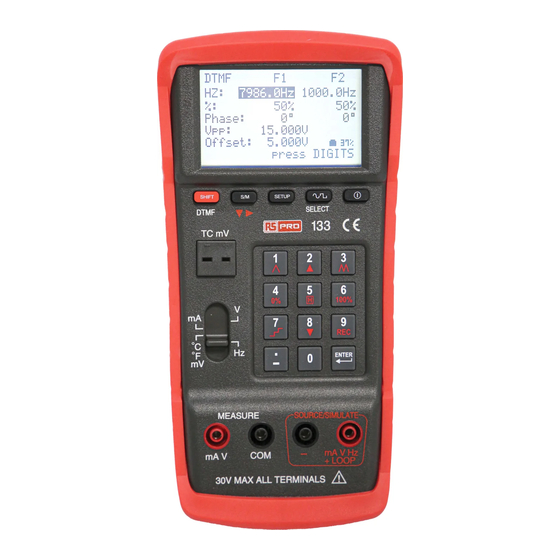
Page 9: Panel Description
Documenting Multifunction Calibrator / EN I. PANEL DESCRIPTION 1. LCM display. 2. ON/OFF button. 3. SELECT button for selecting waveforms (in the Hz function). 4. SETUP button. 5. Numerical key pads; or buttons for special functions. 6. Output/Simulation terminals (for SOURCE). 7. -
Page 10: Operation
Documenting Multifunction Calibrator / EN II. OPERATION 1. Voltage Source 1a. 0V ~ 15V (1) Turn on the power. Turn the sliding switch to V. (2) Press S/M button to select SOURCE (output) mode. (Press once to store it as default mode when power is turned on.) (3) Type in a voltage value (including decimal point);... -
Page 11: 1B. How To Set Up
Documenting Multifunction Calibrator / EN Remark: 1. Users are allowed to type in max. 5 digits. 2. Type in a voltage value (including decimal point), press ENTER, then the calibrator will output this voltage value. 3. When the output value is <0, please type in a negative sign first. 4. -
Page 12: 1C. Details For Set Up
Documenting Multifunction Calibrator / EN 1c. Details for set up (1) Press button to select the item you’d like to setup. (2) When the selected item is in reverse video, type in a value. (3) FILE NAME: Type in a name by corresponding to ASCII codes (refer to Appendix 1). -
Page 13: Current Source
Documenting Multifunction Calibrator / EN 2. Current Source 2a-1. 4 ~ 20mA (1) Turn on the power. Turn sliding switch to mA. (2) Press S/M button to select SOURCE (output) mode. (Press once to store it as default mode when power is turned on: when you press the OUTPUT mode can be set as SOURCE.) -
Page 14: 2A-2. Output (4~20Ma) And Facilitating Use With Hart Tm Communicator
Documenting Multifunction Calibrator / EN 2a-2. Output (4~20mA) and Facilitating use with HART Communicator (1) Turn on the power. Turn sliding switch to mA. (2) Press S/M button to select SOURCE (output) mode. (Press to set the OUTPUT mode as SOURCE, HART250 mode Enabled.) (3) Type in a current value (including decimal point);... -
Page 15: 2A-3. Simulating A Transmitter
Documenting Multifunction Calibrator / EN 2a-3. Simulating a Transmitter (1) Turn on the power. Turn sliding switch to mA. (2) Press S/M button to select SOURCE (output) mode. (Press to set the OUTPUT mode as SIMULATE, HART250 mode Disabled.) (3) Type in a current value (including decimal point); then press ENTER. (4) Connect Test leads or Alligator clips to SOURCE terminals (red to +, and black to -). -
Page 16: 2A-4 Simulating Electronic Load (Max. 30V, 24Ma)
Documenting Multifunction Calibrator / EN 2a-4 Simulating Electronic Load (Max. 30V, 24mA) (1) Turn on the power. Turn sliding switch to mA. (2) Press S/M button to select SOURCE (output) mode. (Press to set the OUTPUT mode as SOURCE.) (3) Type in a current value (including decimal point); then press ENTER. (4) Connect Test leads or Alligator clips to SOURCE terminals (red to +, and black to -). -
Page 17: 2A-5 Led Brightness Testing (0~24Ma)
Documenting Multifunction Calibrator / EN 2a-5 LED Brightness Testing (0~24mA) (1) Turn on the power. Turn sliding switch to mA. (2) Press S/M button to select SOURCE (output) mode. (Press to set the OUTPUT mode as SOURCE.) (3) Type in a current value (including decimal point); then press ENTER. (4) Connect Test leads or Alligator clips to SOURCE terminals (red to +, and black to -). -
Page 18: 2B. How To Set Up
Documenting Multifunction Calibrator / EN Remark: 1. Users are allowed to type in max. 5 digits. 2. Type in a current value (including decimal point), press ENTER, then the calibrator will output this current value. 3. When the output value is <0, please type in a negative sign first. 4. -
Page 19: 2C. Details For Set Up
Documenting Multifunction Calibrator / EN 2c. Details for set up (1) Press button to select the item you’d like to setup. (2) When the selected item is in reverse video, type in a value. (3) When setting up the mapping unit for 4mA or 20mA, type in the unit by corresponding to ASCII codes (refer to Appendix 1). -
Page 20: 2D. Mapping Function
Documenting Multifunction Calibrator / EN 2d. MAPPING Function (1) In the SETUP display when users choose YES for MAPPING, the MAPPING function is enabled (2) The display unit will be the same as the one set up by users. For example, for the unit “KW”... -
Page 21: Temperature Source (Thermocouples, ℃&℉)
Documenting Multifunction Calibrator / EN 3. TEMPERATURE SOURCE (THERMOCOUPLES, ℃& ℉ ) 3a. TC Simulating Thermocouple Signals (for Types K, J, E, T, R, S, N, L, U, B, C, and mV Output) (1) Turn on the power. Turn sliding switch to ℃ ℉ mV. (2) Select a TC TYPE in the SETUP display. -
Page 22: 3B. How To Set Up
Documenting Multifunction Calibrator / EN 3b. How to set up (1) Press to enter SETUP function. (2) TC 0%: set up the “starting” temperature for scanning. (refer to SCANNING chapter). (3) TC 100%: set up the “ending” temperature for scanning. (refer to SCANNING chapter). -
Page 23: Frequency (Hz) Output
Documenting Multifunction Calibrator / EN 4. Frequency (Hz) Output 4a. 0.1Vpp ~ 20Vpp , 0.3Hz ~ 20KHz , offset: -5V ~ +5V (1) Turn on the power. Turn sliding switch to Hz. (Press once to store it as default mode when power is turned on.) (2) Press button to select the type of waveform (Sine wave, Square wave, Triangular wave, Truncated sine wave, and User programmable... -
Page 24: 4B. How To Set Up
Documenting Multifunction Calibrator / EN Remark: 1. Users are allowed to type in max. 5 digits. 2. Type in each parameter (including decimal point), press ENTER, then the calibrator will output the parameter values. 3. When the output value is <0, please type in a negative sign first. 4. -
Page 25: 4C. Details For Fine-Tuning Items
Documenting Multifunction Calibrator / EN 4c. Details for fine-tuning items (1) Hz: set up the output frequency. (2) OUTPUT: set up the output voltage (Peak to Peak). (3) OFFSET: set up the output DC bias accurate position. Fine tune this item can output TTL or modulate PWM signal. -
Page 26: Pulse Function
Documenting Multifunction Calibrator / EN 5. Pulse Function 5a. 3.0μS~999.99mS , 0.5Vpp~10Vpp , offset:-5V ~ +5V (1) Turn off the power. Sliding switch turned to Hz. (2) Press button and button at the same time; the display will show a reverse “PULSE” mark which means it already enters into the PULSE function. -
Page 27: 5B. Details For Fine-Tuning Items
Documenting Multifunction Calibrator / EN Remark: 1. Users are allowed to type in max. 6 digits. 2. Type in each parameter (including decimal point), press ENTER, then the calibrator will output the parameter values. 3. When the output value is <0, please type in a negative sign first. 4. -
Page 28: Dtmf (Dual Tone Multi-Frequency)
Documenting Multifunction Calibrator / EN 6. DTMF (Dual Tone Multi-Frequency) 6a. 5Vpp~20Vpp, 0.3Hz~20KHz, offset: -5V~+5V, %: 0~100%, phase: 0~360 ° (1) Turn on the power. Turn sliding switch to Hz. (Press once to store it as default mode when power is turned on.) (2) Press button to enter DTMF mode. -
Page 29: 6B. How To Set Up
Documenting Multifunction Calibrator / EN Remark: 1. Users are allowed to type in max. 5 digits. 2. Type in each parameter (including decimal point), press ENTER, then the calibrator will output the parameter values. 3. When the output value is <0, please type in a negative sign first. 4. -
Page 30: Voltage Input (Measure)
Documenting Multifunction Calibrator / EN 7. Voltage Input (Measure) 7a. -3V ~ 24V (1) Turn on the power. Turn sliding switch to V. (2) Press button to select MEASURE (input) mode. (3) Connect Test leads or Alligator clips to MEASURE terminals (red to +, and black to -). -
Page 31: Current Input (Measure)
Documenting Multifunction Calibrator / EN 8. Current Input (Measure) 8a-1. -4mA ~ 24mA (1) Turn on the power. Turn sliding switch to mA. (2) Press button to select MEASURE (input) mode. (Press to set the OUTPUT mode as SIMULATE.) (3) Connect Test leads or Alligator clips to MEASURE terminals (red to +, and black to -). -
Page 32: 8A-2. Measure And Output Loop Power 24V
Documenting Multifunction Calibrator / EN 8a-2. Measure and Output Loop Power 24V (1) Turn on the power. Turn sliding switch to mA. (2) Press button to select MEASURE (input) mode. (Press to set the OUTPUT mode as SOURCE, as for HART mode users can set it as Enabled or Disabled.) (3) Connect Test leads or Alligator clips to below terminals: Red to “mA V Hz +LOOP”... -
Page 33: 8B. How To Set Up
Documenting Multifunction Calibrator / EN 8b. How to set up (1) Press to enter SETUP function. (2) 4mA: set up the mapping unit for 4mA. (3) 20mA: set up the mapping unit for 20mA. (4) MAPPING: here users can decide if they want MAPPING function. 06/04/2018 Version No. -
Page 34: 8C. Details For Set Up
Documenting Multifunction Calibrator / EN 8c. Details for set up (1) Press button to select the item you’d like to setup. (2) When the selected item is in reverse video, type in a value. (3) When setting up the mapping unit for 4mA or 20mA, type in the unit by corresponding to ASCII codes (refer to Appendix 1). -
Page 35: Temperature Input (Measure)
Documenting Multifunction Calibrator / EN 9. Temperature Input (Measure) 9a. TC Simulating Thermocouple Signals (for Types K, J, E, T, R, S, N, L, U, B, C, and mV Input) (1) Turn on the power. Turn sliding switch to ℃ ℉ mV. (2) Press button to select MEASURE (input) mode. -
Page 36: 9B. How To Set Up
Documenting Multifunction Calibrator / EN 9b. How to set up (1) Press to enter SETUP function. (2) C. J. COMP.: set up the Cold Junction Compensation. (3) TC TYPE: set up the thermocouple type. (4) UNIT: here users can choose ℃ or ℉ . 9c. -
Page 37: Scanning For Source
Documenting Multifunction Calibrator / EN III. SCANNING FOR SOURCE 1. Voltage Scanning for SOURCE 1a. How to setup: (1) Press button to enter SETUP function. (2) V 0%: set up the “starting” voltage for scanning. (3) V 100%: set up the “ending” voltage for scanning. Remark: 1. - Page 38 Documenting Multifunction Calibrator / EN 1b. Functions of Voltage Scanning for SOURCE Press , then the lower left of LCM will display various functions (see the descriptions on below). SHIFT + Functions Ramp scanning 1% 2%..100% 99%..2% 1% Manual Multi-step scanning (increase progressively) Press this button once +25% till it reaches 100% Fast ramp scanning 4% 8%..100% 96%..8% 4% Return to the “starting”...
- Page 39 Documenting Multifunction Calibrator / EN 1c. Example of Connecting Leads (for Rapid and Multi-step Scanning) Connecting Leads for Fast ramp 06/04/2018 Version No. 1...
- Page 40 Documenting Multifunction Calibrator / EN Connecting Leads for Multi-step Scanning 06/04/2018 Version No. 1...
-
Page 41: Current Scanning For Source
Documenting Multifunction Calibrator / EN 2. Current Scanning for SOURCE 2a. How to setup: (1) Press button to enter SETUP function. (2) mA 0%: set up the “starting” current for scanning. (3) mA 100%: set up the “ending” current for scanning. Remark: 1. - Page 42 Documenting Multifunction Calibrator / EN 2b. Functions of Current Scanning for SOURCE Press , then the lower left of LCM will display various functions (see the descriptions on below). SHIFT + Functions Ramp 1% 2%..100% 99%..2% 1% Manual Multi-step scanning (increase progressively) Press this button once +25% till it reaches 100% Fast ramp 4% 8%..100% 96%..8% 4% Return to the “starting”...
- Page 43 Documenting Multifunction Calibrator / EN 2c. Example of Connecting Leads (for Rapid and Multi-step Scanning) Connecting Leads for Fast ramp 06/04/2018 Version No. 1...
- Page 44 Documenting Multifunction Calibrator / EN Connecting Leads for Multi-step Scanning 06/04/2018 Version No. 1...
-
Page 45: Temperature Scanning For Source
Documenting Multifunction Calibrator / EN 3. Temperature Scanning for SOURCE 3a. How to setup: (1) Press button to enter SETUP function. (2) TC 0%: set up the “starting” temperature for scanning. (3) TC 100%: set up the “ending” temperature for scanning. Remark: 1. - Page 46 Documenting Multifunction Calibrator / EN 3b. Functions of Temperature Scanning for SOURCE Press , then the lower left of LCM will display various functions (see the descriptions on below). SHIFT + Functions Ramp 1% 2%..100% 99%..2% 1% Manual Multi-step scanning (increase progressively) Press this button once +25% till it reaches 100% Fast ramp 4% 8%..100% 96%..8% 4% Return to the “starting”...
- Page 47 Documenting Multifunction Calibrator / EN 3c. Example of Connecting Leads (for Ramp and Multi-step Scanning) Connecting Leads for Fast ramp 06/04/2018 Version No. 1...
- Page 48 Documenting Multifunction Calibrator / EN Connecting Leads for Multi-step Scanning 06/04/2018 Version No. 1...
-
Page 49: Data Logging
Documenting Multifunction Calibrator / EN IV. DATA LOGGING 1. The way of logging The data logging function is available for all the ranges except Hz. 1a. How to set up (1) Only under V range, users can set up SAMPLE and FILE NAME. And the setups under V range will be applied to other ranges (mA, …). -
Page 50: Single-Point Data Logging
Documenting Multifunction Calibrator / EN (3) To stop data logging, please repeat the above procedures. To continue data logging, users just have to repeat it again. (4) When users want to logged data for a different mode (SOURCE or MEASURE), they have to clear memory first (and save the data before clearing the memory if necessary, please refer to Software Manual). -
Page 51: Multi-Point Data Logging
Documenting Multifunction Calibrator / EN 2b. Start Data Logging and then “SHIFT” (1) Under any ranges/modes except Hz range, press will show on the left bottom of the display. Press button to start logging single-point data under specified FILE NAME. (2) Under all the ranges/modes, single-point data under the same FILE NAME can be logged together. -
Page 52: Delete Data & Download Data
Documenting Multifunction Calibrator / EN Start Data Logging and then “SHIFT” (1) Under any ranges/modes except Hz range, press will show on the left bottom of the display. Press button to start logging multi-point data per the sampling time set us by users. (2) To stop data logging, please repeat the above procedure. -
Page 53: Remote Pc (Controlling The Calibrator)
Documenting Multifunction Calibrator / EN V. REMOTE PC (CONTROLLING the calibrator) 1. The baud rate between PC and the calibrator is 460800 Bps. 2. Please refer to below list for corresponding the calibrator buttons to the (remote) PC buttons. Calibator ASCII buttons buttons... -
Page 54: Battery Recharging
Documenting Multifunction Calibrator / EN VI. BATTERY RECHARGING Inside the calibrator there is a rechargeable lithium battery. After turning on the power of the calibrator, the display will show the remaining power percentage of the rechargeable battery. When the remaining power percentage of the rechargeable battery is less than 10%, we suggest users to recharge the battery by using the AC power adaptor provided along with the calibrator. -
Page 55: Electrical Specifications
Documenting Multifunction Calibrator / EN VII. ELECTRICAL SPECIFICATIONS (23+/- 5 ℃ , 10 minutes after turning on the power) mA (source) ( Vopen > 15V) Range Resolution Accuracy of Reading 0.005mA to 4mA +/-0.03% +/- 5dgts 4mA to 20mA +/-0.03% +/-3dgts 20mA to 24mA +/-0.03% +/-5dgts V (source) (maximum load 1mA, short circuit protection <... - Page 56 Documenting Multifunction Calibrator / EN Voltage Peak to Peak for Sine Wave (Vpp, 0.3~20KHz, 50% duty cycle, sine wave, 0V offset) Range(V) Resolution Accuracy of Reading 0.1 to 20V 0.001V 5% +/- 0.3V Voltage Peak to Peak for Non-Sine Wave (Vpp, 0.3~20KHz, 0V offset) Range(V) Resolution...
- Page 57 Documenting Multifunction Calibrator / EN DTMF (Hz) Range (Hz) Resolution Accuracy of Reading 0.3 to 99.999 0.1Hz 0.002Hz 10.00 to 999.99 0.1Hz 0.02Hz 1000.0 to 9999.9 0.1Hz 0.2Hz 10000 to 20000 DTMF (%) Range (%) Resolution Accuracy of Reading 0% ~ 100% DTMF (Phase Angle) Range (°)
- Page 58 Documenting Multifunction Calibrator / EN Temperature, Thermocouples (source and measure, 0.1 C & 0.1 F Resolution, Internal Cold Junction Compensation, thermocouple accuracy not included, 3 minutes after plugging in thermocouples.) °C °F Range Accuracy Range Accuracy -200 to -150 -382 to -238 -150 to 0 -238 to 32...
-
Page 59: General Specifications
Documenting Multifunction Calibrator / EN VIII. GENERAL SPECIFICATIONS AC Power Adaptor: AC 110V or AC 220V, 50/60Hz input. DC 15V / 0.5A output. Dimension: 214.0(L) x 98.7(W) x 56.0(H) mm 8.4" (L) x 3.9" (W) x 2.2" (H) Weight: 650g / 22.9oz (Batteries included) 0℃... -
Page 60: Appendix 1)Ascii Code List
Documenting Multifunction Calibrator / EN (Appendix 1)ASCII code list Decimal System ASCII Decimal System ASCII > " & , : 06/04/2018 Version No. 1... - Page 61 Documenting Multifunction Calibrator / EN Decimal System ASCII Decimal System ASCII < ∘ 凸 μ Λ △ 千 万 元 丹 ² ∞ Є ∩ ± ≧ ≦ 06/04/2018 Version No. 1...
- Page 62 Documenting Multifunction Calibrator / EN Decimal System ASCII Decimal System ASCII α β γ δ ε ζ η Θ ⺄ К λ μ ν ζ 〇 π ρ σ τ υ Φ χ ψ ω Γ Σ Φ Ω 06/04/2018 Version No. 1...
-
Page 63: Limited Warranty
Documenting Multifunction Calibrator / EN Limited Warranty This meter is warranted to the original purchaser against defects in material and workmanship for 3 years from the date of purchase. During this warranty period, RS Components will, at its option, replace or repair the defective unit, subject to verification of the defect or malfunction. - Page 64 Documenting Multifunction Calibrator / EN Africa RS Components SA P.O. Box 12182, Vorna Valley, 1686 20 Indianapolis Street, Kyalami Business Park, Kyalami, Midrand South Africa www.rs-components.com Asia RS Components Pte Ltd. 31 Tech Park Crescent Singapore 638040 www.rs-components.com China RS Components Ltd. Suite 23 A-C East Sea Business Centre Phase 2...
Need help?
Do you have a question about the RS-133 and is the answer not in the manual?
Questions and answers