
Related Manuals for Videotec DCMX9828

Summary of Contents for Videotec DCMX9828
- Page 1 MANUALE D’USO ____________________________ OPERATING INSTRUCTIONS ____________________________ MANUEL D’INSTRUCTIONS ____________________________ BEDIENUNGSANWEISUNG...
- Page 4 MANUALE D’USO...
-
Page 5: Table Of Contents
Ogni cura é stata posta nella raccolta e nella verifica della documentazione contenuta in questo manuale: tuttavia il produttore non può assumersi alcuna responsabilità derivante dall’utilizzo della stessa. Lo stesso dicasi per ogni persona o società coinvolta nella creazione e nella produzione di questo manuale. Pag. 1 DCMX9828... -
Page 6: Introduzione
• L’apparecchio si considera disattivato soltanto quando l’alimentazione é disinserita e i cavi di collegamento con altri dispositivi sono stati rimossi • Per l’assistenza tecnica rivolgersi esclusivamente al personale tecnico autorizzato • Conservare con cura il presente manuale per ogni futura consultazione Pag. 2 DCMX9828... -
Page 7: Dati Di Marcatura
• Miniricevitore di comandi DTMRX: ricevitore digitale a 11 funzioni, consente il controllo di base di un brandeggio motorizzato (orizzontale e verticale, ottiche, autopan). Indirizzabile singolarmente fino a 64 unità. • • Miniricevitore di comandi MICRODEC: ricevitore digitale a 8 funzioni (orizzontale, verticale, zoom e focus). Indirizzabile fino a 32 unità. Pag. 3 DCMX9828... -
Page 8: Esempio Di Installazione
2 fili per la eventuale trasmissione al ricevitore successivo nelle configurazione in cascata (doppino telefonico twistato, sezione 0,22 mm.² AWG 24) Nota: la distanza massima del collegamento é di circa 15 m in RS232; 1500 m in Current Loop. Pag. 4 DCMX9828... -
Page 9: Installazione
Descrizione della marcatura. Non effettuare per nessun motivo alterazioni o collegamenti non previsti in questo manuale: l’uso di apparecchi non idonei può portare a gravi pericoli per la sicurezza del personale e dell’impianto. Pag. 5 DCMX9828... -
Page 10: Configurazione Del Controllore Di Comunicazioni Seriali Dcmx
Si consiglia di procedere con ordine alla configurazione dei parametri, per evitare problemi di installazione. La configurazione consiste nell’impostare: 1) Modalità di ricezione di ciascun ingresso (RS232/Current Loop) 2) Baudrate della comunicazione Jumpers di configurazione Nello schema seguente identificare i jumpers di configurazione ed il DIP switch U6: Pag. 6 DCMX9828... -
Page 11: Configurazione Dell'ingresso N.1
Dove agire : DIP switch U6, interruttore 2 Impostazioni : 9600 baud 1200 baud Gli interruttori 3 e 4 sono usati per i test dell’apparecchio e non devono mai essere modificati: DIP 3 sempre OFF DIP 4 OFF: DCMX Pag. 7 DCMX9828... -
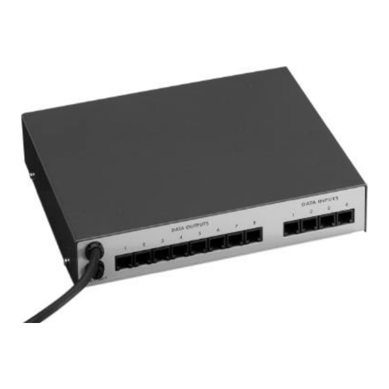
Page 12: Connettori E Collegamenti
La tastiera DCS2/DCMT8, il controllore DCMX ed i ricevitori DTMRX/DTRX/MICRODEC possono essere collegati direttamente tramite cavo telefonico fornito dal fabbricante, per la verifica in laboratorio del funzionamento delle apparecchiature: DTRX DTRX DCMX DCMT8 DCS2 Pag. 8 DCMX9828... - Page 13 Collegamento Current Loop: max 1500 m DCMX DTMRX/DTRX/MICRODEC GND CL Rosso -------------- Verde GND CL TX CL Giallo ---------------Nero RX CL Collegamento RS232: distanza max 15 metri DCMX DTMRX/DTRX/MICRODEC GND RS232 Verde -------- Rosso GND RS232 TX RS232 Nero------------Giallo RX RS232 DCMX Pag. 9 DCMX9828...
-
Page 14: Accensione E Spegnimento
Tensione: 230 V~, 50/60 Hz (riferirsi ai dati di marcatura) Potenza: 10 W Fusibile di protezione: 63 mA 250V T Temperatura di funzionamento: da 0°C a 40°C Dimensioni: 220 x 40 x 180 mm Peso: 1.750 g Pag. 10 DCMX9828... - Page 15 OPERATING INSTRUCTIONS...
- Page 16 The documentation contained in this manual has been collected with great care: the manufacturer, however, cannot take any liability for its use. The same thing can be said for any person or company involved in the creation and production of this manual. Pag. 1 DCMX9828...
- Page 17 • The appliance is completely off-line only when the plug is diconnected and the cables connected to other appliances have been removed • For after-sale service call only authorised technical staff. • Keep this manual close to hand for any future reference Pag. 2 DCMX9828...
- Page 18 • Mini receiver driver DTMRX: 11-function digital receiver, allowing the control of pan & tilt motors (horizontal and vertical, zoom lenses, autopan). It can be individually addressed up to 64 units. • Mini receiver driver MICRODEC: 8-function digital receiver (horizontal, vertical, zoom and focus). It can be adressed up to 32 units. Pag. 3 DCMX9828...
- Page 19 2 wires for the control unit reception (twisted pair cable, section 0,22 mm.² AWG 24) 2 wires for possible transmission to the following receiver in cascade configurations (twisted pair cable, section 0,22 mm.² AWG 24) Note: the maximum connection distance is about 15 m in RS232; 1500 m in Current Loop. Pag. 4 DCMX9828...
- Page 20 Identification data. Do not carry out any modification or connections which are not provided for in this manual: the use of improper appliances may seriously compromise the safety of the personnel and the installation. Pag. 5 DCMX9828...
- Page 21 Proceed in an orderly manner with the parameter configuration, so as to avoid installation problems. The configuration consists in selecting: 1) Receiving mode (RS-232 or Current Loop) for each input. 2) Communication Baudrate. Configuration jumpers In the following scheme, identify the configuration jumpers and the DIP switch U6: Pag. 6 DCMX9828...
- Page 22 Baud rate RECEPTION Where to operate: DIP switch U6, switch 2 Selections: 9600 baud 1200 baud The switches 3 and 4 are used for the appliance control and must not be changed: DIP 3 always OFF DIP 4 OFF Pag. 7 DCMX9828...
- Page 23 The DCS2/DCMT8 keyboard, the DCMX controller and the DTMRX/DTRX/MICRODEC receivers can be connected together by telephone cable supplied by the manufacturer, for a laboratory check of the appliance running: DTRX DTRX DCMX DCMT8 DCS2 Pag. 8 DCMX9828...
- Page 24 DCMX DTMRX/DTRXMICRODEC GND CL Red -------------- Green GND CL TX CL Yellow ------------Black RX CL RS232 connection: max distance 15 metres DCMX DTMRX/DTRXMICRODEC GND RS232 Green -------- Red GND RS232 TX RS232 Black ----------Yellow RX RS232 DCMX Pag. 9 DCMX9828...
- Page 25 Power supply : 230 V~, 50/60 Hz (refer to identification data) Power consumption : 10 W Protection fuses: 63 mA 250V T Operative temperature : from 0°C to 40°C Dimensions: 220 x 40 x 180 mm Weight: 1.750 g Pag. 10 DCMX9828...
- Page 26 MANUEL D’INSTRUCTIONS...
- Page 27 La même chose vaut pour chaque personne ou société impliquées dans la création et la production de ce manuel. Pag. 1 DCMX9828...
- Page 28 • L’appareil est désactivé seulement quand la prise d’alimentation est débranchée et les câbles de raccordement avec d’autres dispositifs ont été enlevés. • Pour le service après-vente s’adresser exclusivement à personnel technique autorisé. • Conserver soigneusement ce manuel pour toute consultation ultérieure Pag. 2 DCMX9828...
- Page 29 • Minirécepteur de commandes DTMRX: récepteur numérique à 11 fonctions, il permet le contrôle de base d’une tourelle motorisée (horizontale et verticale, objectif, autopan). Adressable individuellement jusqu’à 64 unités. • Minirécepteur de commandes MICRODEC: récepteur numérique à 8 fonctions (horizontale, verticale, zoom et focus). Adressable jusqu’à 32 unités. Pag. 3 DCMX9828...
- Page 30 2 fils pour l’éventuelle transmission au récepteur suivant en configurations en ligne bus (boucle téléphonique, section 0,22 mm² AWG 24) Note: la distance max. de raccordement est de 15 m environ en RS232; 1500 m en Boucle de Courant. Pag. 4 DCMX9828...
- Page 31 Caractéristiques techniques . Ne jamais effectuer de modifications ou de raccordements non prévus dans ce manuel: l’emploi d’appareils non appropriés peut compromettre sérieusement la sécurité des personnes et de l’installation. Pag. 5 DCMX9828...
- Page 32 Procéder par ordre dans la configuration des paramètres, afin d’éviter des problèmes d’installation. La configuration consiste à sélectionner: 1) Modalité de réception (RS232/Boucle de Courant) 2) Baudrate de la communication Pontets de configuration Dans le schéma suivant, identifier les pontets de configuration et le DIP switch U6: Pag. 6 DCMX9828...
- Page 33 Où l’on dot agir: DIP switch U6, interrupteur 2 Sélections: 9600 baud 1200 baud Les interrupteurs 3 et 4 sont employés pour le contrôle de l’appareil et ne doivent jamais être modifiés: DIP 4 OFF DIP 3 Toujours Pag. 7 DCMX9828...
- Page 34 Le pupitre DCS2/DCMT8, le contrôleur DCMX et les récepteurs DTMRX/DTRX/MICRODEC peuvent être raccordés directement par câble téléphonique fourni par le fabricant, pour la verification en laboratoire du fonctionnement des appareils: DTRX DTRX DCMX DCMT8 DCS2 Pag. 8 DCMX9828...
- Page 35 GND CL Rouge -------------- Vert GND CL TX CL Jaune ------------- Noir RX CL Raccordement RS232: distance max 15 mètres DCMX DTMRX/DTRX/MICRODEC GND RS232 Vert -------- Rouge GND RS232 TX RS232 Noir -------- Jaune RX RS232 DCMX Pag. 9 DCMX9828...
- Page 36 Alimentation: 230 V~, 50/60 Hz (se rapporter aux caractéristiques techniques) Puissance: 10 W Fusible de protection: 63 mA 250V T Température de fonctionnement: de 0°C à 40°C Dimensions: 220 x 40 x 180 mm Poids: 1.750 g Pag. 10 DCMX9828...
- Page 37 BEDIENUNGSANWEISUNG...
-
Page 38: Inhalt
Die Dokumentation in diesem Handbuch wurde sorgfältig ausgeführt und überprüft, dennoch kann der Hersteller keine Haftung bei der Verwendung übernehmen. Dasselbe gilt für jede Person oder Gesellschaft, die bei der Schaffung oder Produktion von diesem Handbuch miteinbezogen ist Seite 1 DCMX9828... -
Page 39: Einführung
• Das Gerät ist erst dann deaktiviert, wenn der Stromstecker ausgesteckt ist und die Anschlußkabel zu anderen Vorrichtungen entfernt werden • Sich für den technischen Kundendienst ausschließlich an autorisiertes Fachpersonal wenden. • Das vorliegende Handbuch ist zum Nachschlagen gut aufzubewahren Seite 2 DCMX9828... -
Page 40: Betriebseigenschaften Auf Den Datenschildern
• Minibefehls-Empfänger DTMRX: Digital-Empfänger mit 11 Funktionen, gestattet die Basis-Bedienung einer motorisierten Schwenkvorrichtung (horizontal und vertikal, Linsen, Autopan). Einzeln an bis zu 64 Einheiten adressierbar • Minibefehls-EmpfängerMICRODEC: Digital-Empfänger mit 8 Funktionen (horizontal, vertikal, zoom und focus). Einzeln an bis zu 32 Einheiten Seite 3 DCMX9828... -
Page 41: Installationsbeispiel
2 Drähte zum Empfang von der Steuerungseinheit (Doppelschnur, Querschnitt 0,22 mm.² AWG 24) 2 Drähte zur eventuellen Übertragung an den folgenden Empfänger in der Kaskadenkonfiguration (Doppelschnur, Querschnitt 0,22 mm.² AWG 24) Anmerkung: der Höchstabstand des Anschlusses beträgt ca. 15 m in RS232; 1500 m in Current Loop Seite 4 DCMX9828... -
Page 42: Installation
Etiketten mit den Betriebseigenschaften laut Beschreibung unter dem Kapitel Betriebseigenschaften auf den Datenschildern geprüft werden. Es dürfen keinesfalls Änderungen oder in diesem Handbuch nicht vorgesehene Anschlüsse vorgenommen werden: die Verwendugn ungeeigneter Geräte kann zu großer Gefahr für die Sicherheit des Personals und der Anlage führen. Seite 5 DCMX9828... -
Page 43: Konfiguration Der Einheit Für Serielle Kommunikationen Dcmx
Es empfiehlt sich, vorschriftsmäßig bei der Konfiguration der Parameter vorzugehen, um Installationsprobleme zu vermeiden. Die Konfiguration besteht darin: 1) Empfangsmodalität jedes Eingangs (RS232 / Current Loop) 2) Kommunikations-Baudrate einzustellen Konfigurations-Anschlüsse Im folgenden Schema die Konfigurationsjumpers und das DIP Switch U6 identifizieren: Seite 6 DCMX9828... -
Page 44: Konfiguration Des Einganges Nr.1
Baud rate Empfang Eingriffspunkt: DIP switch U6, Schalter 2 Einstellungen: 9600 baud 1200 baud Die Schalter 3 und 4 sind für die Geratsprüfung zu verwenden und deswegen sind sie nie zu verändern: DIP 3 immer OFF DIP 4 OFF Seite 7 DCMX9828... -
Page 45: Verbinder Und Anschlüsse
Konfigurationshandbuch Bezug genommen wird. Die Tastatur DCS2/DCMT8, die Einheit DCMX und die Empfänger DTMRX/DTRX/MICRODEC können direkt mittels vom Hersteller gelieferten Telefonkabel angeschlossen werden, um die Funktionstüchtigkeit der Geräte im Labor zu überprüfen: DTRX DTRX DCMX DCMT8 DCS2 Seite 8 DCMX9828... - Page 46 GND CL Rot -------------- Grün GND CL TX CL Gelb --------- Schwarz RX CL Anschluß RS232: Abstand max 15 Meter DCMX DTMRX/DTRX/MICRODEC GND RS232 Grün -------- Rot GND RS232 TX RS232 Schwarz --- Gelb RX RS232 DCMX Seite 9 DCMX9828...
-
Page 47: Einschalten Und Ausschalten
Verbinder eingesteckt ist. angeschlossen Technische Eigenschaften Spannung: 230 V~, 50/60 Hz (siehe Betriebsdaten auf den Datenschildern) Leistung: 10 W Schutzsicherung: 63 mA 250V T Betriebstemperatur: von 0°C bis 40°C Maße: 220 x 40 x 180 mm Gewicht: 1.750 g Seite 10 DCMX9828...
Need help?
Do you have a question about the DCMX9828 and is the answer not in the manual?
Questions and answers