Advertisement
Quick Links
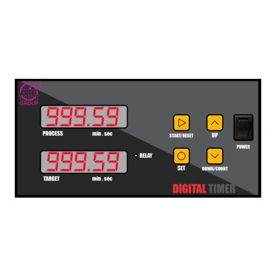
DIGITAL TIMER: tA-02T
Features:
1. Easy steps to program and set Target
Time.
2. Two separate 5 digit displays are
provided for editing the count time and
displaying the target time.
3. Provision to display number of
successful time counts.
4. Provision of an alarm after counting is
done.
5. Power On start switch is provided.
6. External Output AC socket provided.
7. Front keypad setting.
8. Table top mounting
Specifications:
Parameters
Display Type
Display Configuration
Display Colour
Relay Contact
Range
Operations Modes
Reset
Counting Direction
Supply Voltage
Size(W x H x D)
Mounting Type
Operating
Temperature
Specifications
LED
5 digit dual display
(mmm:ss)
RED
1 C/O SPST
0 – 999 min
0 –59 sec
On delay
Reset button
Power Interruption
Down
240V AC
190 x 95 x 65 mm
Table Top
0 °C to 50 °C
Key Functions:
Key
START/RESET Key -
1. Start time count.
2. Reset the timer when key is
long press.
SET KEY -
1. Enter into Time Setting
Mode when key is long
press.
UP Key -
To increment value.
DOWN/COUNT Key -
1. To decrement value.
2. To display number of
successful time counts.
Display Description:
DdDisplay5555555D
d
Function
Description
READY - timer is
ready to start
SET – enter into set
mode
END – process end
indication
COUNT – indicates
succesful number
of process
Advertisement

Related Manuals for TA tA-02T


Summary of Contents for TA tA-02T
- Page 1 DIGITAL TIMER: tA-02T Features: Key Functions: 1. Easy steps to program and set Target Function Time. START/RESET Key - 2. Two separate 5 digit displays are 1. Start time count. provided for editing the count time and 2. Reset the timer when key is displaying the target time.
- Page 2 Timer Front Panel: C. To reset timer. User Settings: 1. By long Pressing START/RESET while count is in Initially the Digital Timer will show process the timer resets to target value. A. To set Time and Start timer: SAFETY PRECAUTIONS: Step1: Long Press SET key to enter into time setting All safety related codifications, symbols and mode.
- Page 3 3. Cable used for connection to power source, must 2 have across section of 1mm or greater. These wires shall have insulation capacity made of at least 1.5kV. INSTALLATION GUIDELINES: 1. This equipment, being built-in-type, normally becomes a part of main control panel and in such case the terminals do not remain accessible to the end user after installation and internal wiring.
Need help?
Do you have a question about the tA-02T and is the answer not in the manual?
Questions and answers