Advertisement
Quick Links
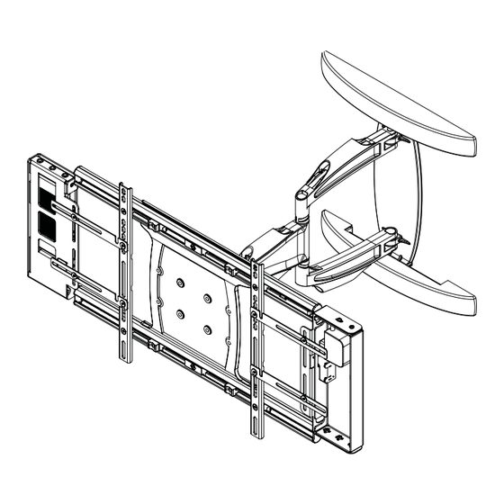
Installation and Assembly:
Wireless Articulating Arm Wall Mount for 42" to 60" Flat Panel
Displays
Model: WL-SA761PU-200
Maximum Load Capacity: 130 lbs (59 kg)
2300 White Oak Circle • Aurora, Il 60502 • (800) 865-2112 • Fax: (800) 359-6500 • www.peerless-av.com
ISSUED: 08-24-12 SHEET #: 180-9036-3 10-31-12
Advertisement

Related Manuals for peerless-AV WL-SA761PU-200


Summary of Contents for peerless-AV WL-SA761PU-200
- Page 1 Wireless Articulating Arm Wall Mount for 42" to 60" Flat Panel Displays Model: WL-SA761PU-200 Maximum Load Capacity: 130 lbs (59 kg) 2300 White Oak Circle • Aurora, Il 60502 • (800) 865-2112 • Fax: (800) 359-6500 • www.peerless-av.com ISSUED: 08-24-12 SHEET #: 180-9036-3 10-31-12...
-
Page 2: Table Of Contents
Note: Read entire instruction sheet before you start installation and assembly. WARNING • Do not begin to install your Peerless product until you have read and understood the instructions and warnings contained in this Installation Sheet. If you have any questions regarding any of the instructions or warnings, for US customers please call Peerless customer care at 1-800-865-2112, for all international customers, please contact your local distributor. -
Page 3: Parts List
Before you begin, make sure all parts shown are included with your product. Parts List WL-SA761PU-200 Description Qty. Part # A wall arm assembly 095-P1992 B universal adapter bracket 095-P1635-2 C wood screws 520-1243 D concrete anchors 590-0321 E M10 x 15 mm socket head screw... - Page 4 Verify that the Transmitter is set to the appropriate input port. © 2012 Peerless Industries, Inc. Peerless-AV™ is a trademark of Peerless Industries, Inc. All rights reserved. HD Flow™ is a trademark of I Do It, LTD. Other parties’ marks are the property of their respective owners. hdflow.com...
- Page 5 Optional Horizontal Adjustment of Wall Arm on Wall Plate NOTE: If mounting wall arm (A) to wood stud walls, slots on wall plate must align to wood studs. Determine desired location of display center detailed in step 2. Measure the distance from the center of wall arm (A) to desired display center. Loosen four 1/4-20 x 17mm screws using 5mm allen wrench (I).
- Page 6 Installation to Double-Stud Wall WARNING • Installer must verify that the supporting surface will safely support the combined load of the equipment and all attached hardware and components. • Tighten wood screws so that wall plate is fi rmly attached, but do not overtighten. Overtightening can damage the screws, greatly reducing their holding power.
- Page 7 Installation to Solid Concrete or Cinder Block WARNING • When installing Peerless wall mounts on cinder block, verify that you have a minimum of 1-3/8" (35mm) of actual concrete thickness in the hole to be used for the concrete anchors. Do not drill into mortar joints! Be sure to mount in a solid part of the block, generally 1"...
- Page 8 Adapter Bracket Adjustment NOTE: If display has a VESA 400 horizontal mounting pattern, skip to step 4 on page 9. NOTE: For VESA 200x200 or VESA 200x100 mount hole patterns, skip to step 5 on page 12. 1/4-20 x 1.25" SCREWS Remove four 1/4-20 x .6"...
-
Page 9: Wireless Receiver Assembly And Power Module Assembly Installation
Wireless Receiver Assembly and Power Module Assembly Installation NOTE: The Wireless Receiver Assembly and Power Module Assembly position can be interchanged based on the display's connector panel location. Install Wireless Receiver Assembly on the side closest to the connector panel. Loosely attach the small enclosure mounting brackets (S) on the wireless receiver assembly (M) with two 1/4-20 decorative screws (Q) and two 1/4-20 nuts (R) as shown in fi... - Page 10 Installing Adapter Brackets to Display WARNING • Tighten screws so display brackets are fi rmly attached to display. Do not tighten with excessive force. Overtightening can cause stress damage to screws, greatly reducing their holding power and possibly causing screw heads to become detached. Tighten to 40 in. • lb. (4.5 N.M.) maximum torque. •...
- Page 11 NOTE: Wireless Receiver and Power Box removed for clarity. DISPLAY MULTI-WASHER Begin with the longest length screw, hand thread SPACER screw through multi-washer, display brackets (B) SCREW and spacer in that order into display as shown below. Screw must make at least three full turns into the mounting hole and fi...
- Page 12 Wireless Receiver and Power Module Installation VESA 200 x 200 or VESA 200 x 100 Mounting Pattern Remove four 1/4-20 x .6" screws using 5mm allen wrench (I) and loosen two 1/4-20 x 1.25" screws 1/2 turn to allow for display bracket adjustment.
- Page 13 Loosely attach the large enclosure mounting Loosely attach the large enclosure mounting bracket bracket (T) on the wireless receiver assembly (M) (T) on the power module assembly (N) with two 1/4- with two 1/4-20 decorative screws (Q) and two 20 decorative screws (Q) and two 1/4-20 nuts (R) as 1/4-20 nuts (R) as shown.
- Page 14 Slide universal adapter bracket (B) to the opposite side and align second display bracket with second set of display mounting holes. Hand thread screws through the multi-washer, display brackets, enclosure mounting brackets (T) and spacer into display as shown. Tighten all screws. MULTI- SCREW WASHER...
-
Page 15: Wireless Receiver Assembly And Power Module Assembly Setup
Position the wireless receiver assembly (M) and power module assembly (N) approximately 1/4" from the universal adapter (B) as shown. Once in position, tighten the four 1/4-20 decorative screws (Q) using using 4mm allen wrench (L) and a 7/16" open end wrench. Skip to step 8. - Page 16 Untie the wireless receiver power adapter cord and route as shown below. Plug the end of the power adapter into the outlet marked DC on the wireless receiver as shown in detail 5. Coil up the excess cord and secure with a cable tie (P).
- Page 17 Close the top cover of the wireless receiver enclosure, making sure that the IR receiver cord runs underneath the cable opening as shown in fi gure 11.1. Re-install the two #8 screws. #8 SCREWS CABLE OPENING fi g. 11.1 Install the cable tie anchor (U) onto the inside back Plug the power cord from your display into the triple wall of the power module assembly (N).
- Page 18 Position the cable management sheath and secure with two cable ties in the approximate locations shown below and detail 7. Do not overtighten cable ties. DETAIL 6 18 of 23 ISSUED: 08-24-12 SHEET #: 180-9036-3 10-31-12...
-
Page 19: Mounting Flat Panel Display
WARNING • Do not lift more weight than you can handle. Use additional man power or mechanical lifting equipment to safely handle placement of the display. • Do not tighten screws with excessive force. Overtightening can cause damage to mount. Tighten M10 x 15mm screws (E) to 40 in. - Page 20 Adjustment of Flat Panel Display WARNING • M10 x 15mm screws (E) must be securly tightened before changing orientation of wall arm assembly (A). Failure to lock adapter bracket can cause display to come off of mount. FOR PORTRAIT OR LANDSCAPE DISPLAY ORIENTATION: Remove two M5 x 12mm screws, one M5 x 6mm screw and rotation block from top of tilt head as shown in top view and rear view.
-
Page 21: Cable Management
Plug the component cable(s) from your display Plug extension cord (not included) into the tripe tap (HDMI shown) into the wireless receiver. grounded outlet. COMPONENT CABLE EXTENSION CORD Cable Management Snap wall plate covers (F) to top and bottom of NOTE: Make sure extension cord (not included) has wall plate rails as shown. - Page 22 22 of 23 ISSUED: 08-24-12 SHEET #: 180-9036-3 10-31-12 © 2012 Peerless Industries, Inc. Peerless-AV® is a registered trademark of Peerless Industries, Inc. All rights reserved. All other brand and product names are trademarks or registered trademarks of their respective owners.
- Page 23 Peerless Industries, Inc. (“Peerless-AV®”) warrants to original end-users of Peerless-AV® products that Peerless-AV® products will be free from defects in material and workmanship, under normal use, for the periods listed below, from the date of purchase by the original end-user. At its option, Peerless-AV® will repair or replace with new or refurbished products or parts, or refund the purchase price of any Peerless-AV®...
Need help?
Do you have a question about the WL-SA761PU-200 and is the answer not in the manual?
Questions and answers