Table of Contents
Advertisement
Quick Links
Advertisement
Table of Contents

Related Manuals for BeagleBone CANBus Cape


Summary of Contents for BeagleBone CANBus Cape
- Page 1 BeagleBone CANBus Cape System Reference Manual Revision A1 September 28th, 2012...
- Page 2 For any questions, concerns, or issues submit them to support@beagleboardtoys.com BEAGLEBONE CANBUS CAPE DESIGN These design materials referred to in this document are *NOT SUPPORTED* and DO NOT constitute a reference design. Only “community” support is allowed via resources at Beagleboardtoys.com/support...
- Page 3 BeagleBone CANBus Cape System Reference Manual Revision A1 FITNESS FOR A PARTICULAR PURPOSE. THE ENTIRE RISK QUALITY PERFORMANCE OF THE DESIGN MATERIALS IS WITH YOU. SHOULD THE DESIGN MATERIALS PROVE DEFECTIVE, YOU ASSUME THE COST OF NECESSARY SERVICING, REPAIR CORRECTION.
- Page 4 BeagleBone CANBus Cape System Reference Manual Revision A1 BeagleBoardToys provides the enclosed product(s) under the following conditions: This evaluation board/kit is intended for use for ENGINEERING DEVELOPMENT, DEMONSTRATION, OR EVALUATION PURPOSES ONLY and is not considered by BeagleBoardtoys.com to be a finished end- product fit for general consumer use.
- Page 5 System Reference Manual Revision A1 WARRANTY: The BeagleBone CANBus Cape is warranted against defects in materials and workmanship for a period of 90 days from purchase. This warranty does not cover any problems occurring as a result of improper use, modifications, exposure to water, excessive voltages, abuse, or accidents.
-
Page 6: Table Of Contents
System Reference Manual Revision A1 Table of Contents FIGURES ..............................7 TABLES ................................ 7 INTRODUCTION..........................9 CHANGE HISTORY .........................10 ..........................10 HANGE ISTORY BEAGLEBONE CANBUS CAPE OVERVIEW ................11 ..........................11 ESCRIPTIONS .............................12 ............................12 EPAIRS FEATURES AND SPECIFICATIONS ....................13 ......................14 OMPONENT OCATIONS CAN B ........................14... -
Page 7: Figures
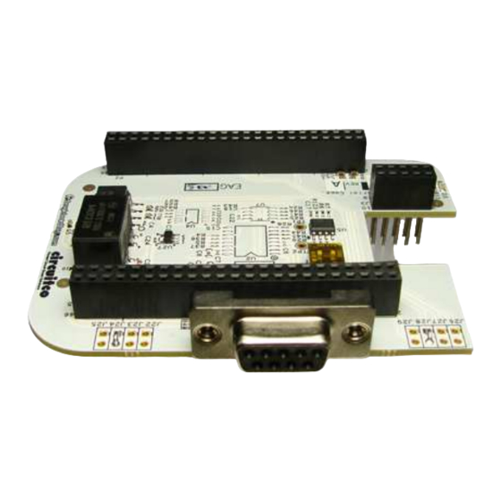
Figure 1. The BeagleBone CANBus Cape ..............11 Figure 2. Key Components ................... 14 Figure 3. BeagleBone CANBus Cape High Level Block Diagram ......16 Figure 4. CAN Transceiver Circuit ................17 Figure 5. UART Selection Circuit ................18 Figure 6. - Page 8 BeagleBone CANBus Cape System Reference Manual Revision A1 NOTES Page 8 of 21...
-
Page 9: Introduction
System Reference Manual Revision A1 Introduction This document is the System Reference Manual for the BeagleBone CANBus Cape, an add-on board for the BeagleBone. This document is intended as a guide to assist anyone purchasing or who are considering purchasing the board to understand the overall design and usage of the BeagleBone CANBus Cape from the system level perspective. -
Page 10: Change History
BeagleBone CANBus Cape System Reference Manual Revision A1 Change History Change History Table 1 tracks the changes made for each revision of this document. Table 1. Change History Changes Date Initial release. 09/28/2012 Page 10 of 21... -
Page 11: Beaglebone Canbus Cape Overview
BeagleBone CANBus Cape Overview Descriptions The BeagleBone CANBus Cape makes use of DCAN1 interface of the AM335x processor to provide a Controller Area Network (CAN) interface that meets the specifications of ISO11898. The CAN Bus interface can be accessed via a standard D- Sub 9 female serial connector. -
Page 12: In The Box
System Reference Manual Revision A1 In The Box The final packaged BeagleBone CANBus Cape product will contain the following items: 1 BeagleBone CANBus Cape Repairs If you feel the board is in need of repair, follow the RMA Request process found at http://www.beagleboardtoys.com/support/rma... -
Page 13: Features And Specifications
Revision A1 Features and Specifications This section covers the specifications of the BeagleBone CANBus Cape and provides a high level description of the major components and interfaces that make up the board. Table 2 provides a list of the BeagleBone CANBus Cape’s features. -
Page 14: Key Component Locations
Key Components CAN Bus Interface The BeagleBone CANBus Cape uses an RSZ-3.305HP to provide isolated power sources for the CAN transceiver ISO1050. ISO1050 is a galvanically isolated CAN transceiver that isolates grounds and prevents noise currents from entering local ground. The bus side of the transceiver is connected to a D-Sub 9 connector and provides an option to install a terminal resistor. -
Page 15: Power Indicator
BeagleBone CANBus Cape System Reference Manual Revision A1 Power Indicator The BeagleBone CANBus Cape features an LED (D3) to indicate that power is applied to the cape. This LED is green when lit. Mechanical Specifications Size: 4.00” x 2.50” Layers: PCB thickness: .062”... -
Page 16: System Architecture And Design
System Reference Manual Revision A1 System Architecture and Design This section provides a high level description of the design of the BeagleBone CANBus Cape and its overall architecture. System Block Diagram Figure 3 is the high level block diagram of the BeagleBone CANBus Cape. -
Page 17: Isolated Power And Ground
UART port of AM335X; these signals are required to be at 3.3V voltage level. The CANBus Cape provides an option to install a terminal resistor for CAN bus signals. The CAN High and CAN Low signals are connected to pin 7 and pin 2 of D-Sub connector J1. -
Page 18: Eeprom
EEPROMs are required for all Capes sold in order for them to operate correctly when plugged in the BeagleBone. The EEPROM used on this cape is the same one as is used on the BeagleBone, a CAT24C256. The CAT24C256 is a 256 kb Serial CMOS EEPROM, internally organized as 32,768 words of 8 bits each. -
Page 19: Eeprom Address
BeagleBone CANBus Cape System Reference Manual Revision A1 Figure 6. BeagleBone CANBus Cape EEPROM 5.5.1 EEPROM Address In order for each Cape to have a unique address, a board ID scheme is used that sets the address to be different depending on the order in which it is stacked onto the main board. -
Page 20: Mechanical Information
BeagleBone CANBus Cape System Reference Manual Revision A1 Mechanical Information This section provides information on the mechanical aspect of the BeagleBone CANBus Cape. Figure 7 is the dimensions of the BeagleBone CANBus Cape. Figure 7. BeagleBone CANBus Cape Dimensions Drawing... -
Page 21: Design Materials
BeagleBone CANBus Cape System Reference Manual Revision A1 Design Materials Design information can be found at BeagleBoardToys wiki: http://beagleboardtoys.com/wiki/index.php?title=BeagleBone_CANBus Provided there is: Schematic in PDF Schematic in OrCAD Manufacturing files o PCB Gerber o PCB Layout (Allegro) Bill of Materials...
Need help?
Do you have a question about the CANBus Cape and is the answer not in the manual?
Questions and answers