Table of Contents
Advertisement
Quick Links
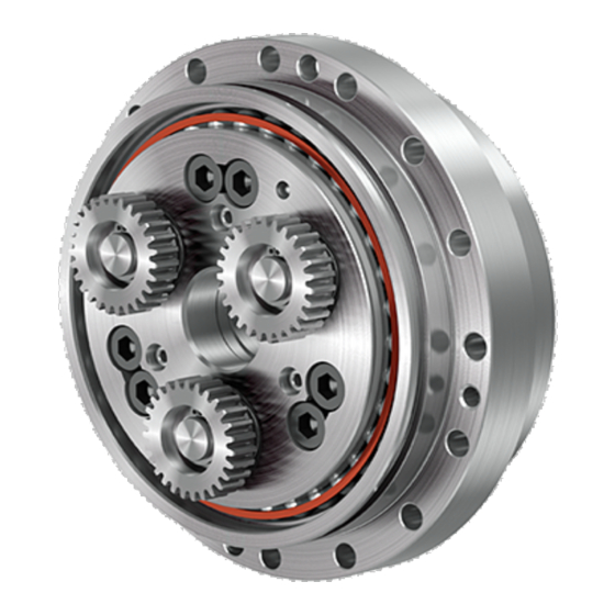
Precision Reduction Gear
N
series
Operation Manual
<Applicable model>
RV-N△
above indicates the torque code.
△ above indicates the series code.
For the applicable models, refer to "Model" indicated on the shipping label of the product.
This manual must be thoroughly read and understood before using the product.
Be sure to deliver this operation manual to the system manager and the person in
charge of the operation.
Keep this manual in the specified location so that it can be immediately referred to
whenever necessary.
®
TM
RV
ERD15003B
Oct 1, 2016
Advertisement
Table of Contents


Need help?
Do you have a question about the RV N Series and is the answer not in the manual?
Questions and answers