Table of Contents
Advertisement
Quick Links
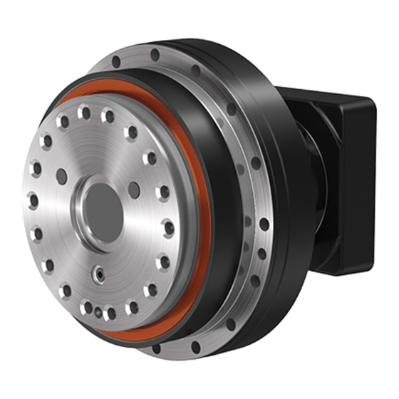
Precision Reduction Gear
High Precision Gearhead
RD2
Operation Manual
<Applicable Model Code>
RDS-006E, RDR-006E
RDS-020E, RDR-020E, RDP-020E
RDS-040E, RDR-040E, RDP-040E
RDS-080E, RDR-080E, RDP-080E
RDS-160E, RDR-160E, RDP-160E
RDS-320E, RDR-320E, RDP-320E
For the applicable model codes, refer to "Model" indicated on the shipping label of the product.
This manual must be thoroughly read and understood before using the product.
Be sure to deliver this operation manual to the system manager and the person in
charge of the operation.
Keep this manual in the specified location so that it can be immediately referred to
whenever necessary.
®
Series
RDS-010C, RDR-010C, RDP-010C
RDS-027C, RDR-027C, RDP-027C
RDS-050C, RDR-050C, RDP-050C
RDS-100C, RDR-100C, RDP-100C
RDS-200C, RDR-200C, RDP-200C
RDS-320C, RDR-320C, RDP-320C
RV
TM
ERD15029A
2016/10/01
Advertisement
Table of Contents

Subscribe to Our Youtube Channel
Related Manuals for Nabtesco RV RD2 Series


Summary of Contents for Nabtesco RV RD2 Series
- Page 1 ® Precision Reduction Gear High Precision Gearhead Series Operation Manual <Applicable Model Code> RDS-006E, RDR-006E RDS-010C, RDR-010C, RDP-010C RDS-020E, RDR-020E, RDP-020E RDS-027C, RDR-027C, RDP-027C RDS-040E, RDR-040E, RDP-040E RDS-050C, RDR-050C, RDP-050C RDS-080E, RDR-080E, RDP-080E RDS-100C, RDR-100C, RDP-100C RDS-160E, RDR-160E, RDP-160E RDS-200C, RDR-200C, RDP-200C RDS-320E, RDR-320E, RDP-320E RDS-320C, RDR-320C, RDP-320C For the applicable model codes, refer to “Model”...
-
Page 2: Table Of Contents
Contents Contents Important Information ......................i 1. Intended use of this product ........................i 2. Rules to ensure safe use of this product ....................i 3. Sharing of hazard information with users....................ii 4. Product disposal ............................ii 5. Other important notes ..........................ii About This Manual ...................... - Page 3 Contents Chapter 6 Operation ....................28 6.1. Checking before operation ........................28 6.2. Running-in operation ..........................28 6.3. Precautions for operation ......................... 28 Chapter 7 Maintenance and Inspection ..............31 7.1. Precautions on maintenance ........................31 7.2. Daily inspection ............................31 7.3.
-
Page 4: Important Information
Failure to do so could cause injury or damage to the reduction gear. Rules to ensure safe use of this product It is impossible for Nabtesco Corporation (referred to as “Nabtesco” hereafter) to foresee any potential hazards related to this product and hazards caused by human errors or peripheral devices. -
Page 5: Sharing Of Hazard Information With Users
Important Information Observe the relevant laws, regulations, ordinances, and bylaws. Observe the relevant laws, regulations, ordinances, and bylaws enacted by the related countries and local governments. Prevention of accidents • To prevent accidents, do not perform any procedures not noted in this manual. Also, do not use this product for any purposes other than those noted at the beginning of this manual. -
Page 6: About This Manual
English, the customer is responsible for conducting safety training and giving operation instructions to those workers. Copyrights The copyright for this manual belongs to Nabtesco Corporation. Unauthorized reprinting, reproduction, copying, or translation of this manual in whole or in part is strictly prohibited. -
Page 7: Warranty
Warranty Warranty 1. In the case where Nabtesco confirms that a defect of the Product was caused due to Nabtesco’s design or manufacture within the Warranty Period of the Product, Nabtesco shall repair or replace such defective Product at its cost. The Warranty Period shall be from the delivery of the Product by Nabtesco or its distributor to you (“Customer”) until the end of one (1) year thereafter, or the end of two thousand... -
Page 8: Glossary
Glossary Glossary Rated service life The lifetime resulting from the operation with the rated torque and the rated output speed is referred to as the “rated service life”. Allowable acceleration/deceleration torque When the machine starts or stops, the load torque to be applied to the reduction gear is larger than the constant-speed load torque due to the effect of the inertia torque of the rotating part. -
Page 9: Chapter 1 About Safety
Chapter 1 About Safety Chapter 1 About Safety The safety precautions noted in this chapter should be used as guidelines to prevent injury of workers who perform transportation, installation, operation, and maintenance of this product, as well as damage to the product. -
Page 10: General Precautions
Chapter 1 About Safety 1.3. General precautions This section describes general precautions for safe use of this product. For precautions concerning transportation, installation, operation, maintenance, and inspection, be sure to confirm the contents of the relevant chapter. Do not modify or disassemble the reduction gear in a manner not described in this manual. Failure to do so could cause injury or damage to the reduction gear. -
Page 11: Chapter 2 Product Overview
Chapter 2 Product Overview Chapter 2 Product Overview This chapter describes an overview of this product. 2.1. Name of each section This section provides an explanation of the name of each section. • If the shape of the actual section differs from the illustration below, refer to the catalog, separately provided “Outer dimensions”... - Page 12 Chapter 2 Product Overview <Pulley input type> RDP- Case Output shaft (shaft) Oil seal on the output side Hole for installing reduction gear Motor flange Input unit Hexagon socket head cap screw seal washer hexagon socket head cap plug (Tapped hole “A” for Hexagon socket head cap plug injecting/draining (Tapped hole “B”...
- Page 13 Chapter 2 Product Overview <Pulley input type> RDP- Middle flange Case Hole for installing reduction Oil seal on the output side Output shaft (shaft) Oil seal in the hollow Label section Hexagon socket head cap plug (Tapped hole “B” for injecting/draining grease) Hexagon socket head cap plug...
-
Page 14: Parts Codes Of Catalog Products
2.3. Lubricant The specified lubricant is filled before shipping. • When replacing the lubricant, be sure to use the Nabtesco-specified lubricant. For purchase of the lubricant, contact our service representative. • Do not mix it with other lubricants. Table 2-1... -
Page 15: Chapter 3 Transportation And Storage Of Product
Chapter 3 Transportation and Storage of Product Chapter 3 Transportation and Storage of Product This chapter describes the transportation and storage of this product. 3.1. Transportation • For the catalog products described in “2.2. Parts codes of catalog products”, refer to the weights of the reduction gears listed in Table 3-1 and transport the product in an appropriate way. -
Page 16: Storage
Chapter 3 Transportation and Storage of Product 3.2. Storage To avoid rust, corrosion, or deterioration of the sealing material, etc., and collapse of stored packing boxes, store the product in the following location. • Location where the ambient temperature is between -10°C to 40℃. •... -
Page 17: Chapter 4 Preparations For Installation
Chapter 4 Preparations for Installation Chapter 4 Preparations for Installation This chapter describes the preparation for installing this product. Before designing the equipment, take care regarding the following precautions. • When the reduction gear is used for human transportation equipment, install an effective safety unit as a fail-safe mechanism, in case of an unexpected failure in the reduction gear. -
Page 18: Preparation Of Required Components
Chapter 4 Preparations for Installation 4.2. Preparation of required components • The following components and materials are required for installing this product. Check the components/materials and prepare them at each customer’s site. • If the shape of the actual section differs from the illustration below, refer to the separately provided “Outer dimensions”... - Page 19 Select the appropriate bolt length based on the mounting dimensions of the components prepared by the customer and the reduction gear. • Prepare the following bolts recommended by Nabtesco: Hexagon socket head cap screw JIS B 1176: 2006 Strength class JIS B 1051: 2000 12.9...
- Page 20 Chapter 4 Preparations for Installation 4.2.3. Serrated lock washer for hexagon socket head cap screw Prepare the following serrated lock washer for hexagon socket head cap screw recommended by Nabtesco: Name: Belleville spring washer (made by Heiwa Hatsujyo Industry Co., Ltd.)
-
Page 21: Unpacking
Chapter 4 Preparations for Installation 4.3. Unpacking Check the following points when unpacking. • Before using this product, check the contents of the packing box and confirm that all the ordered items are included. • Check the top and bottom direction of the packing box and unpack it. ... - Page 22 Chapter 4 Preparations for Installation 4.3.1. Checking the contents • Check the shipping label to confirm that it matches the product you have ordered. the contents of the packing box match the items in the illustration below when unpacking. • Confirm that RDS-040E-153-B2-CB-1B ...
-
Page 23: Lifting Of This Product
Chapter 4 Preparations for Installation 4.3.2. Label indication A label is attached to the main unit of this product. Model Company logo Serial No. QR code (Reading this QR code will display our Website URL and the serial number.) Logo of Precision Reduction Gear RV Fig. - Page 24 Chapter 4 Preparations for Installation Handling bolt size/Hollow shaft series Table 4-6 Handling bolt Weight (kg) Model code Nominal size × pitch Qty. Straight*1 Right angle*1 Pulley (mm) RD -010C 10 to 22 12 to 23 RD -027C M6 × 1.0 17 to 28 18 to 30 RD -050C...
-
Page 25: Chapter 5 Installation
The following are the bolt tightening torques specified by Nabtesco. Be sure to check when tightening the bolts. -
Page 26: Installation Work
Chapter 5 Installation 5.1.2. When installing the motor flange onto the input unit Table 5-2 Nominal size × pitch M6 × 1.0 M8 × 1.25 M12 × 1.75 (mm) Tightening torque 12.1 ± 0.61 29.4 ± 1.47 102 ± 5.10 (Nm) 5.1.3. - Page 27 Chapter 5 Installation • When you order the motor flange mounting type, the product may be delivered with a motor flange already mounted. In such a case, it may not be possible to install the product in the customer’s equipment as it is, depending on the installation method and tools to be used (Fig. 5-1). Check the condition of your equipment and install the product in the correct procedure.
- Page 28 Chapter 5 Installation (1) When the product can be installed as is Perform steps 1 to 4 by taking care regarding the following precautions. Step 1 • Align the mounting holes of the reduction gear with the positions of the tapped holes for the case installation component, and then attach the reduction gear to the specified position.
- Page 29 Chapter 5 Installation Step 4 Attach the shaft installation component to the reduction gear. • • Confirm that the centering shaft of the reduction gear is correctly fitted into the centering hole of the shaft installation component. • Check that there is no foreign matter adhering to the mounting surface. •...
- Page 30 Chapter 5 Installation (2) When the product cannot be installed with the motor flange already mounted Perform steps 1 to 5 by taking care regarding the following precautions. Step 1 Loosen the four hexagon socket head cap screws securing the motor flange, remove the motor flange •...
- Page 31 Chapter 5 Installation Note If the leaking liquid sealant is mixed into the reduction gear, it could cause deterioration of performance, such as abnormal noise, vibration, and torque irregularity. Also, if the liquid sealant adheres to the lip of the oil seal, it could cause leakage of the lubricant. ...
- Page 32 Chapter 5 Installation Note If there is foreign matter adhering to the mounting surface, the mounting surface of the reduction gear may be deformed, which could cause deterioration of performance, such as abnormal noise and torque irregularity and durability. Step 5 •...
- Page 33 Chapter 5 Installation Important If the slits of the bushing and coupling are not aligned, proper tightening force cannot be achieved. When using the bushing with a V groove on the circumference, orient the V groove toward the reduction gear side.
- Page 34 Chapter 5 Installation Step 5 • Make sure that the mounting surfaces of the servomotor and motor flange are in close contact. If either of the surfaces is tilting or there is a gap, remove the servomotor and repeat Step 4. •...
- Page 35 Chapter 5 Installation (2) For the pulley input type Install the pulley using the keyway on the input shaft of the reduction gear and the tap hole on the tip. Note Design the pulley so that the moment load applied to the tip of the input shaft is less than the allowable moment.
-
Page 36: Chapter 6 Operation
Chapter 6 Operation Chapter 6 Operation This chapter describes the operation of the product. 6.1. Checking before operation After installing this product in the customer’s device, check the following points before starting operation. • Components are fixed with each other correctly. •... - Page 37 Chapter 6 Operation Output speed Set the maximum output speed and maximum operating speed for the servomotor as follows. Servomotor maximum output speed (maximum operating speed) / Actual reduction ratio £ Reduction gear maximum allowable output speed Solid series Table 6-1 Maximum allowable output speed Actual...
- Page 38 Chapter 6 Operation Hollow shaft series Table 6-2 Maximum allowable output speed Actual Rated Output Straight Input Right angle Model code reduction Speed Pulley input (rpm) input ratio (rpm) (rpm) (rpm) RD -010C 99.82 141.68 RD -027C 233.45 152.6 RD -050C 196.2 239.8 100.5...
-
Page 39: Chapter 7 Maintenance And Inspection
Chapter 7 Maintenance and Inspection Chapter 7 Maintenance and Inspection This chapter describes how to perform maintenance and inspection. 7.1. Precautions on maintenance Keep away from the rotation section during maintenance/inspection of the device currently in operation. Otherwise, you could be caught by the rotation section, which will result in serious injury. ... -
Page 40: Precautions When Handling The Lubricant
Chapter 7 Maintenance and Inspection 7.3. Precautions when handling the lubricant This section describes the precautions when handling lubricants. Before handling the lubricant, read the precautions described on the container of the lubricant and use it correctly. Improper use could impair your health. ... -
Page 41: Lubricant Replacement
40°C (the area in the right diagram), the state of the lubricant should be checked in advance and the grease replaced earlier as necessary. For the lubricants specified by Nabtesco, refer to “2.3. Lubricant”. Ambient temperature (°C) Fig. 7-1 7.4.2. - Page 42 Chapter 7 Maintenance and Inspection Plug size and tightening torque Table 7-4 Tapped hole “A” for Tapped hole “B” for Tapped hole “C” for Tapped hole “D” for Frame number injecting/draining grease injecting/draining grease injecting/draining grease injecting/draining grease Hexagon socket head cap 006E screw M6 seal washer...
- Page 43 Chapter 7 Maintenance and Inspection For the straight and pulley input type Perform steps 1 to 12 by taking care regarding the following precautions. Step 1 • Rotate and position the output shaft of the reduction gear so that the tapped holes for injecting/draining grease are located diagonally.
- Page 44 Chapter 7 Maintenance and Inspection Tapped hole “B” for Injector injecting/draining grease Inject grease. Drain grease. Tapped hole “A” for injecting/draining grease Fig. 7-3 Step 6 • Inject the lubricant until it overflows from the upper tapped hole for injecting/draining grease on the drain side.
- Page 45 Chapter 7 Maintenance and Inspection For the right angle input type Perform steps 1 to 9 by taking care regarding the following precautions. • The reduction gear main unit is separated from the right angle input unit internally. Fill the lubricant into the reduction gear main unit using the tapped holes “A”...
- Page 46 Chapter 7 Maintenance and Inspection Step 6 • Attach the plugs and parts removed in step 3 above to the tapped holes for injecting/draining grease “A” and “B” with the specified tightening torque. (Reference: Table 7-4 “Plug size and tightening torque”) Replace with new seal tape.
-
Page 47: Troubleshooting Checksheet
Make sure the required number of bolts are tightened uniformly with the specified tightening torque. Make sure the reduction gear, motor, or your company’s components are not installed at a slant. Make sure the specified amount of Nabtesco-specified lubricant has been added. Make sure there are no problems with the motor’s parameter settings. -
Page 48: Contact Information
594 Icchoda, Katada-cho, Tsu, Mie 514-8533, Japan TEL: +81-59-237-4672 FAX: +81-59-237-4697 Nabtesco, VIGOGREASE, RV are registered trademarks or trademarks of Nabtesco Corporation. The contents of this manual are subject to change without prior notice. The PDF data of this manual can be downloaded from the following website.
Need help?
Do you have a question about the RV RD2 Series and is the answer not in the manual?
Questions and answers