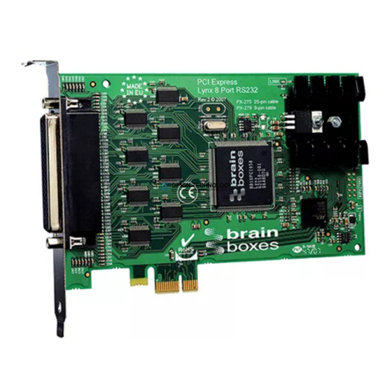
Brainboxes Quad Port RS232 Introduction Manual

Brainboxes Quad Port RS232 Introduction Manual

Hide thumbs Also See for Quad Port RS232:
Table of Contents

Advertisement

Quick Links

232
Q u ad P o rt R S 23 2 &
Ly n x 8 P ort R S 23 2

Advertisement

Table of Contents
loading
Need help?

Need help?

Do you have a question about the Quad Port RS232 and is the answer not in the manual?

Questions and answers

Summary of Contents for Brainboxes Quad Port RS232

  • Page 1 Q u ad P o rt R S 23 2 & Ly n x 8 P ort R S 23 2...
  • Page 2 Guarantee. FULL 36 MONTHS GUARANTEE. BRAIN BOXES guarantee your Serial Port Card for a full 36 months from purchase, parts and labour, provided it has been used in the specified manner. In the unlikely event of failure return your interface to BRAIN BOXES or to your Dealer, with proof of purchase, who will determine whether to repair or replace this product with an equivalent unit.
  • Page 3 AT QUAD AND LYNX RS232 Introduction AT QUAD 4 PORT AND LYNX 8 PORT RS232 MANUAL OUTLINE CONTENTS Chapter 1. Serial Solutions Software Chapter 2. At Quad 4 Port RS232 Hardware Configuration Chapter 3. At Lynx 8 Port RS232 Hardware Configuration Chapter 4.
  • Page 4 Introduction AT QUAD AND LYNX RS232 Chapter 4 - How to install your card into a PC, after configuration a step by step guide to installing the configured card in PC expansion slots. Chapter 5 - AT Quad 4 Port and AT Lynx 8 Port Software Configuration Guide, details on how to setup the serial solutions software provided with the cards in Windows 3.x, Windows 95, Windows NT, OS/2.x, OS/2...
  • Page 5 AT QUAD AND LYNX RS232 Introduction Index CHAPTER 1..............1 Introduction................1 Introducing Serial Solution Software......... 1 Serial Solutions For DOS ............2 Terminal Emulation Program............. 3 Additional Sample 8 Port Software..........4 Serial Solutions For Windows 3.x..........4 Serial Solutions For Windows 95 ..........
  • Page 6 Introduction AT QUAD AND LYNX RS232 Serial Port Bank Address Configuration ........43 Serial Port IRQ Interrupt Jumper Selection......49 Shared Interrupt Setup............50 Shared IRQ Interrupt Jumper Selection........56 Shared Interrupt Mechanism............ 57 One Lynx Card Systems............57 CHAPTER 4...............
  • Page 7 AT QUAD AND LYNX RS232 Introduction Configuring Ports 5 to 8 (8 Port Cards Only) ......110 Completing Card Setup............111 Modifying Settings for a Multiport Card......113 Deleting Settings for a Multiport Card ........114 Deleting All Multiport Card Settings ........115 Configuring Ports in OS/2 Version 2.x and OS/2 Warp...117 Configuring Ports in SCO Unix / Xenix.
  • Page 8 Introduction AT QUAD AND LYNX RS232 This Page Left Intentionally Blank Intro 6...
  • Page 9 AT QUAD AND LYNX RS232 Serial Solutions CHAPTER 1 SERIAL SOLUTION SOFTWARE. Introduction. This chapter is a brief introduction to the Serial Solutions software package that is bundled with the Quad 4 Port and Lynx 8 Port RS232 card. Introducing Serial Solution Software The perfect partner for any Serial Port is Serial Solutions Software! Serial Solutions is a fully featured suite of programs designed to squeeze the most from PC serial communications.
  • Page 10: Chapter 1 Page 2

    Serial Solutions AT QUAD AND LYNX RS232 Serial Solutions For DOS Serial Solutions for DOS consists of the following programs:- NewCOM.sys A device driver, it supporting COM1 to COM16, allowing 16 serial ports to be used under DOS. It also includes an interrupt handler for enhanced performance with user definable buffer sizes.
  • Page 11: Chapter 1 Page 3

    AT QUAD AND LYNX RS232 Serial Solutions debug information. Use these FIRST, base your sample applications on them. Source code, make files and compiled ready to run programs supplied. TERM programs A suite of larger terminal emulation programs written in C (Cterm), Assembly language (Aterm), Pascal (Pasterm), BASIC (BASterm) and FORTRAN (FORterm) show how to access the NEWBIOS routines as well as the...
  • Page 12: Chapter 1 Page 4

    Serial Solutions AT QUAD AND LYNX RS232 In addition the terminal programs recognise an impressive set of commands, that may be executed automatically or interactively. The commands include features to enable Echoing of transmitted and received data, set up the serial port parameters, set substitution characters and string for both in coming and outgoing data, execute terminal batch files, transmit from and receive to disk, execute DOS commands from within the terminal program.
  • Page 13: Chapter 1 Page 5

    AT QUAD AND LYNX RS232 Serial Solutions Port.DLL Enhanced Control Panel applet. Allows configuration of extra serial ports from the Windows Control Panel. Supports single as well as multiport cards using shared interrupts. BbLynx.drv Replacement for COMM.DRV. LynxAPI.dll Enhancement to the Windows Comms API's allowing support for more than 9 ports.
  • Page 14: Cabling Requirements

    Serial Solutions AT QUAD AND LYNX RS232 NT to drive multiport cards. Serial Solutions for Windows NT consists of the following programs:- Multiport.cpl Control panel applet which allows the simple configuration of all ports on a multiport card simultaneously. Mulport.hlp Help file for the above control panel applet The Comtest.exe Program Comtest is a short but invaluable program that is used to...
  • Page 15: Card Features

    AT QUAD AND LYNX RS232 Quad Hardware Configuration Guide CHAPTER 2 AT QUAD 4 PORT RS232 HARDWARE CONFIGURATION. Introduction. This chapter explains how to configure the AT QUAD 4 PORT RS232 in a PC compatible, giving details for address and IRQ jumper selection.
  • Page 16: Chapter 2 Page 8

    QUAD Hardware Configuration Guide AT QUAD AND LYNX RS232 The AT QUAD 4 PORT RS232 has the following features: Baud Rate: 50 Baud to 115200 Baud. Word Length: 5, 6, 7 or 8 bits. Parity: Even, Odd, None, Mark or Space. Start Bit: 1 start bit always sent.
  • Page 17: Chapter 2 Page 9

    AT QUAD AND LYNX RS232 Quad Hardware Configuration Guide Figure 2-2. 9 and 25 pin RS232 pinouts 9 Pin: PIN 1 - DATA CARRIER DETECT (DCD) PIN 6 - DATA SET READY (DSR) PIN 2 - RECEIVED DATA (RXD) PIN 7 - REQUEST TO SEND (RXD) PIN 3 - TRANSMITTED DATA (TXD) PIN 8 - CLEAR TO SEND (CTS) PIN 4 - DATA TERMINAL READY (DTR)
  • Page 18: Chapter 2 Page 10

    QUAD Hardware Configuration Guide AT QUAD AND LYNX RS232 Figure 2-3a). AT Quad 4 Port RS232 Layout COM1 Present Only MULTI CARD LINK P#1 P#2 P#3 P#4 COM 4 COM 3 COM 2 COM 1 BANK CARD ID P#1 P#2 P#3 P#4 BANK BANK ADDR ESS SISR Card Settings...
  • Page 19: Chapter 2 Page 11

    AT QUAD AND LYNX RS232 Quad Hardware Configuration Guide Figure 2-3b). AT Quad 4 Port RS232 Layout COM1 and COM2 Present MULTI CARD LIN K P#1 P#2 P#3 P#4 COM 4 COM 3 COM 2 COM 1 BANK CARD ID P#1 P#2 P#3 P#4 BANK BANK ADDRESS SISR...
  • Page 20: Chapter 2 Page 12

    QUAD Hardware Configuration Guide AT QUAD AND LYNX RS232 Figure 2-3c). AT Quad 4 Port RS232 Layout Digiboard PC/4 Configuration MULTI CARD LINK P#1 P#2 P#3 P#4 COM 4 COM 3 COM 2 COM 1 BANK CARD ID P#1 P#2 P#3 P#4 BANK BANK ADDRESS SISR Card Settings...
  • Page 21: Chapter 2 Page 13

    AT QUAD AND LYNX RS232 Quad Hardware Configuration Guide AT Quad 4 Port Specifications: Dimensions: 4.2 x 6.3 in, 106 x 160 mm I/O Connection: 37 way female D connector to 4 serial ports Serial Port 1: 9 pin Male D type. Serial Port 2: 9 pin Male D type.
  • Page 22: Chapter 2 Page 14

    QUAD Hardware Configuration Guide AT QUAD AND LYNX RS232 several cards by following the information in Chapter 6 “Quad and Lynx Shared Interrupt Mechanisms” Table 2 -1 AT Quad 4 Port card configuration Card Settings COM 1 COM1 & Digiboard Present COM2 Present PC/4...
  • Page 23: Serial Port Setup

    AT QUAD AND LYNX RS232 Quad Hardware Configuration Guide The Ideal Situation. If your serial communications packages are configurable for I/O address and interrupt then set all the serial ports in your system so that each serial port has its own separate I/O address, and interrupt not used by any other device in the PC.
  • Page 24 QUAD Hardware Configuration Guide AT QUAD AND LYNX RS232 Figure 2-4. Serial Port Jumper Address Block Jumper Port Address Normal IRQ Allocation COM4 COM3 COM4 02E8h IRQ 3 (DEFAULT COM2 COM1 SETTING FOR SERIAL 3) BANK COM4 COM3 COM3 03E8h IRQ 3 (DEFAULT COM2 COM1...
  • Page 25: Port Address Settings

    AT QUAD AND LYNX RS232 Quad Hardware Configuration Guide Figure 2-5. Serial Port Bank Address Allocation PORT ADDRESS SETTINGS: 180h 188h 190h 198h ON OFF OFF ON ON ON ON NOT USED FOR BANK SETTINGS Within this 32 byte bank, port 1 - port 4 are decoded consecutively.
  • Page 26: Chapter 2 Page 18

    QUAD Hardware Configuration Guide AT QUAD AND LYNX RS232 Figure 2-6. Valid Quad Port Base Addresses. On Off On On On Off Off On Off On On On Off On On Off On On On On Off On Off On On On On On On Off On On Off Off Off On Off On On Off Off On On Off On On Off On Off...
  • Page 27: Chapter 2 Page 19

    AT QUAD AND LYNX RS232 Quad Hardware Configuration Guide SWITCH On Off Off Off On Off Off On Off Off Off On Off On On Off Off Off On On Off On Off Off Off On On On On Off Off Off Off Off Off On Off Off Off Off Off On On Off Off Off Off On Off On Off Off Off Off On On...
  • Page 28: Chapter 2 Page 20

    QUAD Hardware Configuration Guide AT QUAD AND LYNX RS232 SWITCH Off On Off On On Off Off Off On Off On On Off On Off On Off On On On Off Off On Off On On On On Off On Off On Off Off Off Off On Off On Off Off On Off On Off On Off On Off Off On Off On Off On On...
  • Page 29: Chapter 2 Page 21

    AT QUAD AND LYNX RS232 Quad Hardware Configuration Guide SWITCH Off Off On On Off Off Off Off Off Off Off Off Off Off On On Off Off On On Off Off On On Off Off On On Off Off Off Off Off Off Off Off Off Off Off...
  • Page 30: Normal Use

    QUAD Hardware Configuration Guide AT QUAD AND LYNX RS232 Figure 2-7. I/O Addresses To Avoid. I/O Address Normal Use 0102H VGA Graphics Option Bit 01F0H - 01F7H IDE Hard Disk 0201H - 0201H Game Control Adapter 0278H - 027FH Second Printer Port Adapter 02E1H *** PC ELITE IEEE Board.
  • Page 31: Chapter 2 Page 23

    AT QUAD AND LYNX RS232 Quad Hardware Configuration Guide Serial Port IRQ Interrupt Jumper Selection. The position of the movable jumper on the interrupt jumper block, located in the bottom left hand corner of the card, determines the IRQ vector of the serial ports, configuring the card as IRQ2 - IRQ7, IRQ10 to IRQ12, or IRQ14 to IRQ15.
  • Page 32: Chapter 2 Page 24

    QUAD Hardware Configuration Guide AT QUAD AND LYNX RS232 Figure 2-8. Port IRQ Jumper Block. NORMAL USE OF INTERRUPT H234567 SHARED INTERRUPT FACTORY DEFAULT IRQ 2 EGA/VGA GRAPHIC CARD. Usually free. Only Used by very few graphics cards. IRQ 3 COM 2. IRQ 4 COM 1.
  • Page 33: Chapter 2 Page 25

    AT QUAD AND LYNX RS232 Quad Hardware Configuration Guide switch, labelled SISR, in conjunction with DIP 8 on the BANK ADDR DIP switch is used to select the I/O address of the shared interrupt status register. It may be any address on an 2 byte boundary in the range 0100-03FE Hex.
  • Page 34: Chapter 2 Page 26

    QUAD Hardware Configuration Guide AT QUAD AND LYNX RS232 Figure 2-10. Valid Quad SISR Addresses. 8 DIP 4 DIP 5 SISR Chapter 2 Page 26...
  • Page 35: Chapter 2 Page 27

    AT QUAD AND LYNX RS232 Quad Hardware Configuration Guide SISR Chapter 2 Page 27...
  • Page 36: Chapter 2 Page 28

    QUAD Hardware Configuration Guide AT QUAD AND LYNX RS232 SISR Chapter 2 Page 28...
  • Page 37: Chapter 2 Page 29

    AT QUAD AND LYNX RS232 Quad Hardware Configuration Guide SISR DO NOT USE Chapter 2 Page 29...
  • Page 38: Chapter 2 Page 30

    QUAD Hardware Configuration Guide AT QUAD AND LYNX RS232 Shared IRQ Interrupt Jumper Selection. The SHARED IRQ jumper block is located immediately to the left of the bottom centre of the card. The movable jumper determines which interrupt is called by those serial ports SHARING an interrupt.
  • Page 39: Chapter 2 Page 31

    AT QUAD AND LYNX RS232 Quad Hardware Configuration Guide NOTE: IRQ 0 & 8 - Timer & Clock Interrupts, not on expansion bus IRQ 1 - Keyboard interrupt, not on expansion bus IRQ 9 - Best left Unexplained, not on expansion bus IRQ 13 - Maths coprocessor interrupt, not on expansion bus In order to make use of the shared interrupt settings, the IRQ jumper settings (see the section entitled “Serial Port IRQ jumper...
  • Page 40: Chapter 2 Page 32

    QUAD Hardware Configuration Guide AT QUAD AND LYNX RS232 not be used, it is only required in multi Quad card systems. Refer to Chapter 6 - “Shared Interrupt Mechanisms”, and more specifically the section entitled “Multicard setup” for a more in depth discussion on this subject.
  • Page 41 AT QUAD AND LYNX RS232 LYNX Hardware Configuration Guide CHAPTER 3 AT LYNX 8 PORT RS232 HARDWARE CONFIGURATION. Introduction. This chapter explains how to configure the AT LYNX 8 PORT RS232 in a PC compatible, giving details for address and IRQ jumper selection.
  • Page 42: Chapter 3 Page 34

    LYNX Hardware Configuration Guide AT QUAD AND LYNX RS232 The AT LYNX 8 PORT RS232 has the following features: Baud Rate: 50 Baud to 115200 Baud. Word Length: 5, 6, 7 or 8 bits. Parity: Even, Odd, None, Mark or Space. Start Bit: 1 start bit always sent.
  • Page 43: Chapter 3 Page 35

    AT QUAD AND LYNX RS232 LYNX Hardware Configuration Guide Figure 3-2. 9 and 25 pin RS232 pinouts 9 Pin: PIN 1 - DATA CARRIER DETECT (DCD) PIN 6 - DATA SET READY (DSR) PIN 2 - RECEIVED DATA (RXD) PIN 7 - REQUEST TO SEND (RXD) PIN 3 - TRANSMITTED DATA (TXD) PIN 8 - CLEAR TO SEND (CTS) PIN 4 - DATA TERMINAL READY (DTR)
  • Page 44: Chapter 3 Page 36

    LYNX Hardware Configuration Guide AT QUAD AND LYNX RS232 Figure 3-3a). AT LYNX 8 Port RS232 Layout Com 1 Present: Card COM 1 I R Q 1 5 I R Q 1 4 Settings Only I R Q 1 2 I R Q 1 1 I R Q 1 0 Port #1...
  • Page 45: Chapter 3 Page 37

    AT QUAD AND LYNX RS232 LYNX Hardware Configuration Guide Figure 3-3b). AT LYNX 8 Port RS232 Layout Com 1 and Com 2 Present: Card COM1 & I R Q 1 5 I R Q 1 4 Settings COM2 Only I R Q 1 2 I R Q 1 1 I R Q 1 0 Port #1...
  • Page 46: Chapter 3 Page 38

    LYNX Hardware Configuration Guide AT QUAD AND LYNX RS232 Figure 3-3a). AT LYNX 8 Port RS232 Layout Digiboard PC/8 Defaults: I R Q 1 5 Card Digiboard I R Q 1 4 I R Q 1 2 I R Q 1 1 Settings PC/8 I R Q 1 0...
  • Page 47: Chapter 3 Page 39

    AT QUAD AND LYNX RS232 LYNX Hardware Configuration Guide AT LYNX 8 Port RS232 Specifications: Dimensions: 4.2 x 6.3 in, 106 x 160 mm I/O Connection: 78 way female D connector to 8 serial ports Serial Port 1: 9 pin Male D type. Serial Port 2: 9 pin Male D type.
  • Page 48: Chapter 3 Page 40

    LYNX Hardware Configuration Guide AT QUAD AND LYNX RS232 Configuring The AT LYNX 8 Port RS232 In the state it leaves our factory, the AT LYNX 8 Port RS232 is ready to plug straight into a PC compatible computer. Unless there is GOOD REASON, do not alter its default setting. However, due to the presence of other serial ports in the PC, your card may need configuring to suit your setup.
  • Page 49: Serial Port Configuration

    AT QUAD AND LYNX RS232 LYNX Hardware Configuration Guide Mechanisms” and the sections below concerning shared interrupt settings. iii) Multiple Card Setup. Refer to the sections at the end of Chapter 2 and 3 entitled “One card Quad Systems” and “1 card Lynx Systems” respectively, and also to the section “Multiple card systems”...
  • Page 50: Chapter 3 Page 42

    LYNX Hardware Configuration Guide AT QUAD AND LYNX RS232 allocation jumper block with default settings. Figure 3-4. Serial Port Jumper Address Block Jumper Port Address Normal IRQ Allocation P8ON P7ON COM8 As Bank IRQ 3 (DEFAULT) P6ON P5ON (198h default) P8ON P7ON COM7...
  • Page 51: Chapter 3 Page 43

    AT QUAD AND LYNX RS232 LYNX Hardware Configuration Guide Serial Port Bank Address Configuration This 32 byte bank, shown below in Figure 3-4 with default settings, containing the 8 serial ports, may be any address on an 8 byte boundary in the range 0100-03C0 Hex. e.g. 0100h, 0108h, 0110h, 0200h, 0240h, 0280h, 02C0h, 03C0h etc.
  • Page 52: Chapter 3 Page 44

    LYNX Hardware Configuration Guide AT QUAD AND LYNX RS232 Figure 3-6. Valid Lynx Port Base Addresses. D IP D IP D IP D IP D IP D IP D IP SW IT C H P# 1 P# 2 P# 3 P#4 P #5 P# 6 P# 7 P#8 100 108 100 108 110 100 108 110 118...
  • Page 53: Chapter 3 Page 45

    AT QUAD AND LYNX RS232 LYNX Hardware Configuration Guide D IP D IP D IP D IP D IP D IP D IP SW IT C H P# 1 P# 2 P# 3 P#4 P #5 P# 6 P# 7 P#8 188 190 198 1A0 1A8 1B0 1B8 1C0 190 198 1A0 1A8 1B0 1B8 1C0 1C8 198 1A0 1A8 1B0 1B8 1C0 1C8 1D0...
  • Page 54: Chapter 3 Page 46

    LYNX Hardware Configuration Guide AT QUAD AND LYNX RS232 D IP D IP D IP D IP D IP D IP D IP SW IT C H P# 1 P# 2 P# 3 P#4 P #5 P# 6 P# 7 P#8 248 250 258 260 268 270 278 280 250 258 260 268 270 278 280 288 258 260 268 270 278 280 288 290...
  • Page 55: Chapter 3 Page 47

    AT QUAD AND LYNX RS232 LYNX Hardware Configuration Guide D IP D IP D IP D IP D IP D IP D IP SW IT C H P# 1 P# 2 P# 3 P#4 P #5 P# 6 P# 7 P#8 308 310 318 320 328 330 338 340 310 318 320 328 330 338 340 348 318 320 328 330 338 340 348 350...
  • Page 56: Chapter 3 Page 48

    LYNX Hardware Configuration Guide AT QUAD AND LYNX RS232 Figure 3-7. I/O Addresses To Avoid. I/O Address Normal Use 0102H VGA Graphics Option Bit 01F0H - 01F7H IDE Hard Disk 0201H - 0201H Game Control Adapter 0278H - 027FH Second Printer Port Adapter 02E1H *** PC ELITE IEEE Board.
  • Page 57: Chapter 3 Page 49

    AT QUAD AND LYNX RS232 LYNX Hardware Configuration Guide Serial Port IRQ Interrupt Jumper Selection. The position of the movable jumper on the interrupt jumper block, located in the bottom left hand corner of the card, determines the IRQ vector of the serial ports, configuring the card as IRQ2 - IRQ7, IRQ10 to IRQ12, or IRQ14 to IRQ15.
  • Page 58: Chapter 3 Page 50

    LYNX Hardware Configuration Guide AT QUAD AND LYNX RS232 Figure 3-7. Port IRQ Jumper Block. NORMAL USE OF INTERRUPT H234567 SHARED INTERRUPT FACTORY DEFAULT IRQ 2 EGA/VGA GRAPHIC CARD. Usually free. Only Used by very few graphics cards. IRQ 3 COM 2. IRQ 4 COM 1.
  • Page 59: Chapter 3 Page 51

    AT QUAD AND LYNX RS232 LYNX Hardware Configuration Guide switch, labelled SISR, in conjunction with DIP 8 on the BANK ADDR DIP switch is used to select the I/O address of the shared interrupt status register. It may be any address on an 2 byte boundary in the range 0100-03FE Hex.
  • Page 60: Chapter 3 Page 52

    LYNX Hardware Configuration Guide AT QUAD AND LYNX RS232 Figure 3-8. Valid Lynx SISR Addresses. 8 DIP 4 DIP 5 SISR Chapter 3 Page 52...
  • Page 61: Chapter 3 Page 53

    AT QUAD AND LYNX RS232 LYNX Hardware Configuration Guide SISR Chapter 3 Page 53...
  • Page 62: Chapter 3 Page 54

    LYNX Hardware Configuration Guide AT QUAD AND LYNX RS232 SISR Chapter 3 Page 54...
  • Page 63: Chapter 3 Page 55

    AT QUAD AND LYNX RS232 LYNX Hardware Configuration Guide SISR DO NOT USE Chapter 3 Page 55...
  • Page 64: Chapter 3 Page 56

    LYNX Hardware Configuration Guide AT QUAD AND LYNX RS232 Shared IRQ Interrupt Jumper Selection. The SHARED IRQ jumper block is located immediately to the left of the bottom centre of the card. The movable jumper determines which interrupt is called by those serial ports SHARING an interrupt.
  • Page 65: Chapter 3 Page 57

    AT QUAD AND LYNX RS232 LYNX Hardware Configuration Guide NOTE: IRQ 0 & 8 - Timer & Clock Interrupts, not on expansion bus IRQ 1 - Keyboard interrupt, not on expansion bus IRQ 9 - Best left Unexplained, not on expansion bus IRQ 13 - Maths coprocessor interrupt, not on expansion bus In order to make use of the shared interrupt settings, the IRQ jumper settings (see the section entitled “Serial Port IRQ...
  • Page 66: Chapter 3 Page 58

    LYNX Hardware Configuration Guide AT QUAD AND LYNX RS232 not be used, it is only required in multi Lynx card systems. Refer to Chapter 6 - “Shared Interrupt Mechanisms”, and more specifically the section entitled “Multicard setup” for a more in depth discussion on this subject.
  • Page 67 AT QUAD AND LYNX RS232 Installing the PC Serial Card CHAPTER 4 INSTALLING THE PC SERIAL CARD IN THE COMPUTER. Serial Card Installation. Once the card has been correctly configured then it can be installed in the PC. It is best to make a note of the serial port I/O address selection and IRQ jumper settings for later use.
  • Page 68: Chapter 4 Page 60

    Installing the PC Serial Card AT QUAD AND LYNX RS232 Figure 4-1. Remove Cover Mounting Screws. STEP 2: Then using a screw driver, remove the cover mounting screws on the back panel of the PC system unit. Figure 4-2. Removing The PC Cover. STEP 3: Next, remove the PC's cover by sliding it forward and up.
  • Page 69: Chapter 4 Page 61

    AT QUAD AND LYNX RS232 Installing the PC Serial Card Figure 4-3. Removing Blanking Cover STEP 4: Choose an empty expansion slot. The PC Serial card will fit either a full length or a short slot, a 8 bit PC type slot or a 16 bit AT type slot.
  • Page 70: Chapter 4 Page 62

    Installing the PC Serial Card AT QUAD AND LYNX RS232 STEP 5: Now insert the PC Serial card in the slot. Be careful to ensure that the gold plated PCB fingers fits neatly into the I/O expansion connector. Press down firmly but evenly on the top of the PC Serial card.
  • Page 71: Software Configuration Guide

    AT QUAD AND LYNX RS232 Software Configuration CHAPTER 5 AT QUAD 4 PORT RS232 & AT LYNX 8 PORT RS232 SOFTWARE CONFIGURATION GUIDE Introduction This section contains the quick start software installation procedures for Serial Solutions for DOS, Windows 3.x, Windows 95 and Windows NT(the Serial Solutions installation is discussed in greater detail in the Serial Solutions Manuals, which come bundled with the Quad/Lynx card.) Also included are the software setup for...
  • Page 72: Chapter 5 Page 64

    Software Configuration AT QUAD AND LYNX RS232 addresses. The trick, for the older PC’s, is to get the right addresses into the third and fourth port areas. However, PC’s are not capable of recognising ports above COM4 - specific device drivers are responsible for this.
  • Page 73: Chapter 5 Page 65

    AT QUAD AND LYNX RS232 Software Configuration COM1: 03F8 COM2: 02F8 COM3: <not set> COM4: <not set> LPT1: 03BC LPT2: <not set> LPT3: <not set> Provided that the RS232 installation is attacked in this orderly manner, every thing should work first time. If it does not then check the software selectable communications parameters, Baud rate, Parity, stop bits first, and that the communications program is attempting to access the serial port installed.
  • Page 74: Chapter 5 Page 66

    Software Configuration AT QUAD AND LYNX RS232 Settings for DOS Software. Most users will require that the IRQ is set to correspond to the interrupt used by their serial communications software. Note, that a serial port that is USING interrupts must not share the same IRQ line as another serial port that is USING interrupts AT THE SAME TIME, otherwise some interrupts will be missed.
  • Page 75: Chapter 5 Page 67

    AT QUAD AND LYNX RS232 Software Configuration PC already has COM1 installed on IRQ 4 Lynx card set as COM2 to COM9 All interrupts set to Shared Shared Interrupt set to IRQ 3 The following shows a typical entry for NEWCOM in the CONFIG.SYS file when the PC already has two serial ports installed as COM1 and COM2.
  • Page 76: Chapter 5 Page 68

    Software Configuration AT QUAD AND LYNX RS232 Shared Interrupt set to IRQ 3 The following shows a typical entry for NEWCOM in the CONFIG.SYS file with the Quad port card when the PC already has two serial ports installed as COM1 and COM2. Change the dips to suit, see below.
  • Page 77: Chapter 5 Page 69

    AT QUAD AND LYNX RS232 Software Configuration COM7 is card's port 5 COM8 is card's port 6 COM9 is card's port 7 COM10 is card's port 8 Setting number of Buffers to 10 Setting buffer size in bytes to 512 Figures 1-1 to 1-4 above contains several new command line switches for NewCOM.SYS that are not documented in the earlier Serial Solutions manuals.
  • Page 78: Chapter 5 Page 70

    Software Configuration AT QUAD AND LYNX RS232 Lynx port#4 is mapped as COM5 Lynx port#5 is mapped as COM6 Lynx port#6 is mapped as COM7 Lynx port#7 is mapped as COM8 Lynx port#8 is mapped as COM9 The /B switch, /B 9, works as before and sets the number of buffers to 9.
  • Page 79: Chapter 5 Page 71

    AT QUAD AND LYNX RS232 Software Configuration Sets COM1 to 03F8H and COM2 to 02F8H. For example: /A3,02F8 /A4,02 E8 /A5,0198 /A6,01A0 /A7,01A8 /A8,01B0 /A9,01B8 Is used with the Lynx card to set the I/O address of the serial ports. The above line specifies COM3 to COM9, port#2-8 on the Lynx card.
  • Page 80: Chapter 5 Page 72

    Software Configuration AT QUAD AND LYNX RS232 DigiCHANNEL PC/4 and PC/8. Switch: /D add,I,p1,p2….. Purpose: Set up one or more DigiCHANNEL cards. This command is entirely equivalent with the /L command with which it is interchangeable. One or two /D switches are required for each card, one for each of the two interrupt lines that the card uses.
  • Page 81: Chapter 5 Page 73

    AT QUAD AND LYNX RS232 Software Configuration Flynix-8 FAT-011. Switch: /F i1,p1,p2,p3,p4,i2,p5,p6,p7,p8 Purpose: Set up one or more Flynix-8 cards. One /F switch can be used to set up one or more cards. 'i1' is the interrupt line for ports 1 to 4 on the card. 'p1', 'p2, etc.
  • Page 82: Hardware Handshake

    Software Configuration AT QUAD AND LYNX RS232 Hardware Handshake. Switch: /H [n],[hs] Purpose: Select which hardware handshake type to use on port COMn. 'n' specifies the COM port. If n is not specified the handshake is applied to all serial ports. 'hs' is a number indicating the type of handshake, and 0 is the default.
  • Page 83: Hardware Interrupt

    AT QUAD AND LYNX RS232 Software Configuration Hardware Interrupt. Switch: /I n,i Purpose: Set interrupt lines for COMn. 'n' specifies the COM port. If n is not specified the interrupt line is applied to all ports. 'i' is the interrupt line in the range 2 to 7 and 10 to 15 or, to indicate no interrupt line, -1 or nothing.
  • Page 84: Chapter 5 Page 76

    Software Configuration AT QUAD AND LYNX RS232 IRQ 10 Usually Free. IRQ 11 Usually Free. IRQ 12 Usually Free. IRQ 15 Usually Free. Lynx 8 Port RS232 cards (May also use with Quad cards). Switch: /L add,i,p1,p2... Purpose: Set up one or more Lynx cards. This command is entirely equivalent with the /D command with which it is interchangeable.
  • Page 85: Chapter 5 Page 77

    AT QUAD AND LYNX RS232 Software Configuration Lynx port#7 is mapped as COM8 Lynx port#8 is mapped as COM9 For example: /L 300,7,3,4,5,6 sets up a Lynx card with a status register at 0300H. The card uses interrupt 7 as the shared interrupt line. Ports 1 and 2 are designated as COM3 and COM4, Ports 3 and 4 are designated COM5 and COM6, and all the shared interrupt IRQ 7.
  • Page 86: Buffer Size

    Software Configuration AT QUAD AND LYNX RS232 its own status registers and interrupts. Note that although linked cards can share interrupts, separate cards cannot share any interrupt line. /L 03A0,3,2,3,4,5,6,7,8,9 1st card SISR at 03A0 /L 0300,7,10,11,12,13,14,15,16,17 2nd card SISR at 0300 The interrupt line specified in the /L switch overrides any interrupts set via the /I switch for the same COM ports, because Lynx cards use a slightly different mechanism for interrupts.
  • Page 87: Driver Defaults

    AT QUAD AND LYNX RS232 Software Configuration default values are 17 (DC1) and 19 (DC3) respectively. For example: /X2 or /X3,18,20 If n, the port number, is not given, then XON/XOFF handshaking and any specified handshake characters are set for all ports, as /X or /X,18,20 Driver Defaults.
  • Page 88: Chapter 5 Page 80

    Software Configuration AT QUAD AND LYNX RS232 Buffer Number. The maximum number of pairs of buffers is 6 (that is up to six ports can use buffered I/O). Baud rate etc. These depend on a variety of factors. Ports recognised by the ROM BIOS are reset to 2400 Baud, no parity, 8 data bits and one stop bit when the machine is powered up.
  • Page 89: Chapter 5 Page 81

    AT QUAD AND LYNX RS232 Software Configuration Serial Solutions Installation for Windows 3.x To install the software from the supplied disk, insert the disk and assuming disk drive is drive A:, from Windows Program Manager's File menu choose "Run" and in the Command Line entry window type A:\SETUP (else type the letter of the drive you are installing from, followed by SETUP).
  • Page 90: Serial Port Installation

    Software Configuration AT QUAD AND LYNX RS232 Figure 5-5. Setup Program Main Display. Selecting the Continue" button will start the installation process. When the setup program has finished select the Done button. A Windows restart message will be shown only if the Windows communications driver option has been selected, and you should choose Yes to allow the new driver to run.
  • Page 91: Chapter 5 Page 83

    AT QUAD AND LYNX RS232 Software Configuration Then click on Serial Ports: The following dialogue should then appear: To add entries for a 4 port (QUAD) serial card (which supports interrupt sharing) you will need to add 4 extra COM ports.
  • Page 92: Chapter 5 Page 84

    Software Configuration AT QUAD AND LYNX RS232 default of 3A0, select this from the available choices by selecting the downward pointing arrow in the "SISR Base" entry area. Note: The base address, IRQ, SISR base address and card's port value should be entered correctly or Windows may crash when the serial port is used.
  • Page 93: Changing Serial Port Settings

    AT QUAD AND LYNX RS232 Software Configuration have installed all four ports. It is necessary to restart Windows unless there are other serial ports which are to be added or changed BEFORE using any serial ports, in which case it is possible to restart Windows AFTER these changes are made.
  • Page 94: Chapter 5 Page 86

    Software Configuration AT QUAD AND LYNX RS232 shared interrupt multiport serial cards, ie those WITH special on board hardware that allows interrupt sharing, e.g. the Lynx 8 port or Quad 4 port cards. For each serial port FOUR parameters MUST be set: The I/O address of the serial port card.
  • Page 95: Chapter 5 Page 87

    AT QUAD AND LYNX RS232 Software Configuration to match the base address and IRQ physically set on the serial port cards. The following procedure shows this for previously set ports, but if you wish to add new serial ports, then repeat the steps shown in the section “Serial Port Installation”.
  • Page 96: Restarting Windows

    Software Configuration AT QUAD AND LYNX RS232 For a multiport interrupt sharing card only: f1)Enter/select the SISR base address (default is 3A0). f2)Enter the Card's Port, this is the physical port on the card. For this port COM2 enter Card's Port = 1. This example assumes a 4 port card is being set as COM2, COM3, COM4 and COM5, all sharing IRQ15, with SISR register at 03A0 hex.
  • Page 97: Chapter 5 Page 89

    AT QUAD AND LYNX RS232 Software Configuration changes restart Windows so that the new settings come into effect. Note: Default settings for communications are given whenever the ADD button is used, 9600 baud, no parity, 8 data bits and 1 stop bit.
  • Page 98: Chapter 5 Page 90

    Software Configuration AT QUAD AND LYNX RS232 Serial Solutions Installation for Windows 95 The following steps describe the installation of the Serial Solutions driver for Windows 95, which is supplied on one 3.5” floppy disc. The listed installation procedure assumes that only 1 COM port (COM1) is present.
  • Page 99: Chapter 5 Page 91

    AT QUAD AND LYNX RS232 Software Configuration The Add New Hardware wizard will ask you if you wish Windows to search for your hardware. Click the No radiobutton since Windows cannot find Multiport Serial Solutions serial ports and it will save some time. Click next From the hardware types list on the next page select Ports (COM &...
  • Page 100: Chapter 5 Page 92

    Software Configuration AT QUAD AND LYNX RS232 Select Standard Port Type and then Communications Port, and then click Have Disk. Windows will then ask you for the location of the Serial Solutions files, assuming your floppy drive is designated A:, you will see the following: Chapter 5 Page 92...
  • Page 101: Chapter 5 Page 93

    AT QUAD AND LYNX RS232 Software Configuration After the installation procedure, the Window will display the entry Serial Solutions for Windows 95: Select the Serial Solutions for Windows95 Port. Click next. Windows 95 will then inform you of the settings it has assumed for the new ports.
  • Page 102: Configuring Ports

    Software Configuration AT QUAD AND LYNX RS232 Click finish. Windows will install the selected port. You will then be asked if you wish to re-boot the system. Since the Serial Solution port entries will require some configuration changes after installation select No. N.B.
  • Page 103: Chapter 5 Page 95

    AT QUAD AND LYNX RS232 Software Configuration Select the View devices by type radiobutton, if it is not already selected. Click the + sign to the left of the Ports (COM & LPT) entry in the list. Double click the first of the Serial Solutions ports you have just installed.
  • Page 104: Chapter 5 Page 96

    Software Configuration AT QUAD AND LYNX RS232 If the Input/Output Range setting does not reflect those set on the card (which will most probably be the case) double click the Input/Output Range text on the dialogue. Chapter 5 Page 96...
  • Page 105: Chapter 5 Page 97

    AT QUAD AND LYNX RS232 Software Configuration Use the scroll bars to change the address to that which the port has been set to on the hardware. Click OK. If the Interrupt Request number does not reflect that set on the port, either the separate interrupt allocated to a specific port, or the shared interrupt (if the port is configured to use that) needs to be added instead.
  • Page 106: Chapter 5 Page 98

    Software Configuration AT QUAD AND LYNX RS232 By default the installation will show ‘3A0’ which is the factory shipped default setting. This procedure is carried out for all ports that are to have shared interrupts. The logical port number must be set as detailed in the appropriate hardware manual.
  • Page 107: Chapter 5 Page 99

    AT QUAD AND LYNX RS232 Software Configuration Restarting Windows Whenever certain values have been entered or changed in the hardware settings window, a message prompting to restart Windows will appear. Only after having made ALL the necessary changes restart Windows so that the new settings come into effect. Windows 95™...
  • Page 108: Chapter 5 Page 100

    Software Configuration AT QUAD AND LYNX RS232 Serial Solutions Installation for Windows NT 3.51 & 4 The suggested installation sequence is: 1. Check Windows NT’s I/O Use, to determine which IRQ’s and I/O addresses are already in use on your PC, and thus which are available.
  • Page 109: Chapter 5 Page 101

    AT QUAD AND LYNX RS232 Software Configuration A list of in use IRQ’s is shown (those shown above include a four port multiport card using the shared interrupt of 5). Any interrupt not shown on the list can be used, make a note of a free IRQ and set the card to use it, a list of recommended free IRQ’s is given elsewhere in this manual.
  • Page 110: Chapter 5 Page 102

    Software Configuration AT QUAD AND LYNX RS232 The top pane of this window lists the interrupts (or Vectors) in use on this computer, you need to find an interrupt which is not on this list for your card. The bottom panel lists the physical addresses which are in use on your computer, a free block needs to be found with 8 bytes free for each port that you will be configuring on your card.
  • Page 111: Chapter 5 Page 103

    AT QUAD AND LYNX RS232 Software Configuration • The Card ID (the default for Serial Solutions cards is 0). Each logical card has 8 ports on, so the Card ID is set in units of 1 (0 to 7) for 8 port serial cards and units of 0.5 •...
  • Page 112: Chapter 5 Page 104

    Software Configuration AT QUAD AND LYNX RS232 3. Press OK. 4. Close the Ports applet and then start the Multiport applet. You may now configure the port you have selected using the software as normal. Keep Detected Port You may keep the port automatically created by NT and then omit that port by clearing the check box in the wizard (see later sections for further information) when creating settings for the new card.
  • Page 113: Chapter 5 Page 105

    AT QUAD AND LYNX RS232 Software Configuration This will launch the Serial Solutions Setup Wizard for Windows This introductory screen will warn you if you are running the program without administrator permissions (you are not allowed to continue if this is the case since you cannot alter settings). If all is well it will appear as above.
  • Page 114: Chapter 5 Page 106

    Software Configuration AT QUAD AND LYNX RS232 You will now be shown a list of serial ports which were installed on your computer when NT was started. If you have since installed a serial port without restarting or you have installed a serial port which is not functioning correctly it might not be shown on this list, be aware of this in these situations.
  • Page 115: Chapter 5 Page 107

    AT QUAD AND LYNX RS232 Software Configuration You set the number of ports on your card using the appropriate radio button. This must be the total number of ports on your card, even if you do not want to use all of them (individual ports can be disabled later).
  • Page 116: Chapter 5 Page 108

    Software Configuration AT QUAD AND LYNX RS232 you to configure individual ports. The box in the lower part of the dialogue is for settings shared amongst the ports. These settings follow closely those which may be set on the card itself (these settings must match of course).
  • Page 117: Shared Settings

    AT QUAD AND LYNX RS232 Software Configuration (see below). If for example Base COM is 18 then this port will be COM 19. • If no COM 3 exists, a standard COM 3 will be created, using the COM 3 address and called COM 3. Both of these situations are independent of the IRQ setting.
  • Page 118: Chapter 5 Page 110

    Software Configuration AT QUAD AND LYNX RS232 3. SISR This is the Shared Interrupt Status Register, this is a register which handles shared interrupt events, a valid address must be given. Suitable settings for the SISR are listed elsewhere in this manual. 4.
  • Page 119: Chapter 5 Page 111

    AT QUAD AND LYNX RS232 Software Configuration The configuration for these ports is somewhat different to that for the first four since they cannot be set to a default address (they must be banked or disabled). For each port only two pieces of information are necessary : 1.
  • Page 120: Chapter 5 Page 112

    Software Configuration AT QUAD AND LYNX RS232 These values have not yet been created, to enter them into the registry click Finish. If you want to change any of these settings click the Back button. You may print a copy of this report to the default Windows printer using the Print button.
  • Page 121: Chapter 5 Page 113

    AT QUAD AND LYNX RS232 Software Configuration want to add more ports before restarting then click No and restart the wizard. Modifying Settings for a Multiport Card When card settings have been created you can later modify them using this same control panel. Run this control panel again and when you select Next from the Welcome dialogue, the option screen will show the previously installed card.
  • Page 122: Chapter 5 Page 114

    Software Configuration AT QUAD AND LYNX RS232 A report is then shown as above on the ports configured on the card you have selected. You may print a copy of this report to the default Windows printer using the Print button. On this screen you may change the name of the card (which is optional) or choose Next to change settings.
  • Page 123: Chapter 5 Page 115

    AT QUAD AND LYNX RS232 Software Configuration required port. As in Modify Settings choose the card that you want to delete from the list on the choose function dialogue and the Delete Settings for a Multiport Card option and click Next. You are then shown a report on the card which you have chosen to delete.
  • Page 124: Chapter 5 Page 116

    Software Configuration AT QUAD AND LYNX RS232 You are then given important information on the deleting process and the option to delete or not delete the Permit Share Registry key. This key is important to the operation of multiport cards. If you have other multiport cards in your computer which you did not setup using this Serial Solutions software then you must ensure that the No (leave the PermitShare key enabled) option is enabled,...
  • Page 125 AT QUAD AND LYNX RS232 Software Configuration Configuring Ports in OS/2 Version 2.x and OS/2 Warp. OS/2 provides built in support for up to four serial ports. OS/2 assumes that COM1 is on IRQ4 and that COM2 is on IRQ3. To use COM3 and COM4 ports on AT bus machines it is necessary to include parameters on the DEVICE=COM.SYS statement in the CONFIG.SYS file.
  • Page 126: Chapter 5 Page 118

    Software Configuration AT QUAD AND LYNX RS232 Configuring Ports in SCO Unix / Xenix. This section describes how to install the AT Quad 4 Port RS232 port and the AT Lynx 8 port cards for use with the built in support provided by the SCO Unix and SCO Xenix operating systems.
  • Page 127: Chapter 5 Page 119

    AT QUAD AND LYNX RS232 Software Configuration Table 5-1 - Quad and Lynx card Unix Configurations Quad Card Lynx Card IRQ Vector 4 (COM1) 4 (COM1) BANK address 110-12F hex 110-14F hex Config A SISR address 150-151 hex 150-151 hex IRQ Vector 3(COM2) 3(COM2)
  • Page 128: Chapter 5 Page 120

    Software Configuration AT QUAD AND LYNX RS232 Table 5-2. Quad Port SCO Unix/Xenix Configurations Config (a) Config (b) BANK BANK COM 1 BANK BANK COM 2 BANK BANK COM 3 BANK BANK COM 4 4 (COM 1) 3 (COM 2) IRQ VECTOR 110-12F hex 210-22f hex...
  • Page 129: Chapter 5 Page 121

    AT QUAD AND LYNX RS232 Software Configuration serial (ADM) command, installing card as a Digiboard PC/8 card. This creates the necessary device files, new kernal etc. allowing access to the new terminal ports. Finally reboot the PC using the shutdown (ADM) or reboot (ADM) commands. On power up the card should be recognised as a Digiboard Digiport PC/8 card.
  • Page 130: Chapter 6 Page 122

    Introduction. This chapter discusses the shared interrupt mechanism used on the Lynx 8 and Quad port RS232 cards and the Quad RS422/485 cards. This interrupt system is 100% compatible with that used on the Digiboard PC/8 and PC/4 dumb cards. The extensive range of software written for the Digiboard cards will work with the Lynx 8 and 4 port cards.
  • Page 131: Chapter 6 Page 123

    AT QUAD AND LYNX RS232 Shared Interrupt Mechanisms share a single interrupt line. As well as hardware allowing sharing of a single interrupt, there is an shared interrupt status register. Shared Interrupt Status Register. The shared interrupt status register uses a PRIORITY encoding system.
  • Page 132: Chapter 6 Page 124

    Shared Interrupt Mechanisms AT QUAD AND LYNX RS232 The first interrupt generated causes all successive interrupts to be "hidden" from the SISR, until the interrupt it has been serviced. Later interrupts are prioritised so that those of lower priority have their interrupt "hidden" from the SISR, until the interrupt on the higher priority port has been serviced.
  • Page 133: Chapter 6 Page 125

    AT QUAD AND LYNX RS232 Shared Interrupt Mechanisms Figure 6-2. CARD ID In 1 Lynx Card System. Card ID: Must always set CARD ID = 0 NOTE: Dip 4 not used 1 2 3 4 MultiCard Link: SIGNAL ACTION EXT IN (EXTERNAL INTERRUPT INPUT) SHORT WITH JUMPER (GROUND) SHORT WITH JUMPER...
  • Page 134: Chapter 6 Page 126

    Shared Interrupt Mechanisms AT QUAD AND LYNX RS232 one cable brings the external interrupt IN from boards of the higher priority, and one cable carries the interrupt OUT to boards of a lower priority. Each card has a different CARD ID which identifies which board generated the interrupt.
  • Page 135: Chapter 6 Page 127

    AT QUAD AND LYNX RS232 Shared Interrupt Mechanisms Mixing 4 Port and 8 Port Cards. Any mix of Quad and Lynx port cards can be placed in a system. A pair of 4 port Quad cards can be treated as one eight port Lynx card, any odd 4 port card should be placed as the LAST card in the system with the highest ID.
  • Page 136: Chapter 6 Page 128

    Shared Interrupt Mechanisms AT QUAD AND LYNX RS232 Figure 6-4. Two Lynx Card Connection. CARD #1 CARDID=00 CARD #2 EXT IN CARDID=01 EXT OUT EXT IN EXT OUT LAST LAST Three Card Systems. When three Lynx/Quad cards are in use the first card has its CARD ID set to 0, and its link across LAST and NO.
  • Page 137: Chapter 6 Page 129

    AT QUAD AND LYNX RS232 Shared Interrupt Mechanisms Figure 6-5. Three Lynx Card Connection. CARD #1 CARDID=00 CARD #2 EXT IN CARDID=01 CARD #3 EXT IN EXT OUT CARDID=02 EXT IN EXT OUT LAST EXT OUT LAST LAST Four Or More Card Systems. When four or more Lynx/Quad cards are in use the first card has its CARD ID set to 0.
  • Page 138: Chapter 6 Page 130

    Shared Interrupt Mechanisms AT QUAD AND LYNX RS232 Figure 6-6. Four Or More Lynx Card Connection. CARD #1 CARDID=00 CARD #2 EXT IN CARDID=01 CARD #3 EXT IN EXT OUT CARDID=02 CARD #4 EXT IN EXT OUT CARDID=03 LAST EXT OUT EXT IN LAST EXT OUT...
  • Page 139: Chapter 6 Page 131

    AT QUAD AND LYNX RS232 Shared Interrupt Mechanisms Figure 6-7. Multi Card Interrupt Priority. Port Priority Shared Status Register Reads No Interrupt None FF Hex= 256 decimal. Port 1 Lynx#1 Highest 00 Hex= 0 decimal. CARD ID=0 Port 2 Lynx#1 Highest 01 Hex= 1 decimal.
  • Page 140: Chapter 6 Page 132

    Shared Interrupt Mechanisms AT QUAD AND LYNX RS232 Port 1 Lynx#4 Middle 18 Hex= 24 decimal. CARD ID=3 Port 2 Lynx#4 Middle 19 Hex= 25 decimal. Port 3 Lynx#4 Middle 1A Hex= 26 decimal Port 4 Lynx#4 Middle 1B Hex= 27 decimal Port 5 Lynx#4 Middle 1C Hex= 28 decimal.
  • Page 141 AT QUAD AND LYNX RS232 RS232 Port Cabling CHAPTER 7 RS232 PORT CABLING. Introduction. This chapter gives details of the 9 pin RS232 pin outs, cabling and connections, with information on how to connect the serial ports of two PCs and make a selftest loop back connector. The RS232 Standard.
  • Page 142: Serial Port Pinouts

    RS232 Port Cabling AT QUAD AND LYNX RS232 Serial Port Pin Outs. The pinouts of the 9 and 25 pin Male D connectors are given below. Figure 7-2. Serial Port RS232 Pin Outs. PIN 1 - DATA CARRIER DETECT (DCD) PIN 6 - DATA SET READY (DSR) PIN 2 - RECEIVED DATA (RXD) PIN 7 - REQUEST TO SEND (RXD)
  • Page 143: Chapter 7 Page 135

    AT QUAD AND LYNX RS232 RS232 Port Cabling sense. The cross over cable is simply to ensure that the right signals going out of one RS232 port go into the appropriate lines of the other RS232 port. 9 Pin D Serial Port Connection To Another PC. Suppose we want to connect the AT style 9 pin D Serial Port to the serial port of another IBM PC.
  • Page 144: Chapter 7 Page 136

    RS232 Port Cabling AT QUAD AND LYNX RS232 Figure 7-3. 9 Pin D Serial Port To Other PC Cable. AT SERIAL PORT Side Other PC SERIAL PORT Side. 9 PIN D CONNECTOR 9 PIN D CONNECTOR SCHEMATIC REPRESENTATION: ACTUAL REPRESENTATION: 9 PIN D CONNECTOR 25 PIN D CONNECTOR SCHEMATIC REPRESENTATION...
  • Page 145: Chapter 7 Page 137

    AT QUAD AND LYNX RS232 RS232 Port Cabling 9 Pin D Serial Port To A Modem. If you are connecting a MODEM to a 9 pin D Serial Port then you will NOT need a cross over cable and a straight through cable connected as the 9 to 25 pin adapter given in Figure 7-5.
  • Page 146: Schematic Representation

    RS232 Port Cabling AT QUAD AND LYNX RS232 Figure 7-5. 9 To 25 Way Adapter. This adapter cable makes the AT style 9 pin serial port, look like the standard PC 25 pin serial port. It is NOT a cross over cable! 9 Pin AT SERIAL PORT 25 Pin PC SERIAL PORT 9 Pin Female D Connector...
  • Page 147: Chapter 7 Page 139

    AT QUAD AND LYNX RS232 RS232 Port Cabling The Quad Cable Pinouts The Quad cable consists of a 37 way female D connector attached to 4 25 way Male D connectors. Each of the cables carries 9 cores plus a sheath. Each of the 25 pin D connectors has 9 connections, based on the standard PC serial port configuration.
  • Page 148: Chapter 7 Page 140

    RS232 Port Cabling AT QUAD AND LYNX RS232 PIN36 - DTR#4 is pin 36 of the 37way connector, which corresponds to the DTR function on port 4. Figure 7-7. Quad Cable by 9 and 25 pin D Connector 38 way D connector Pinouts Port Port Port...
  • Page 149: Chapter 7 Page 141

    AT QUAD AND LYNX RS232 RS232 Port Cabling The Lynx Card Octopus Cable Pinouts The Lynx card octopus cable connects a 78 pin Male D connector to 8 26 way Male D connectors. Each of the cables has 9 cores plus a sheath. The sheath each of the 25 way D connectors is connected to the sheath of the 78 way D connector.
  • Page 150: Chapter 7 Page 142

    RS232 Port Cabling AT QUAD AND LYNX RS232 Figure 7-9. Lynx Cable by 9 and 25 pin D Connector 78 way D connector Pinouts Port Port Port Port Pin Function Transmitted Data (TXD) Received Data (RXD) Request To Send (RTS) Clear To Send (CTS) Data Set Ready (DSR) Ground (GND)
  • Page 151 AT QUAD AND LYNX RS232 Index Index 16450 / 16550 ................1, 6, 7, 33, 117 8250........................ 1 adapter ....................137, 138 Add New Hardware..................90, 91 address / addresses ..............63, 64, 97, 117 asynchronous .....................7, 33 baud / baud rate..................2, 6, 7, 33 baud rate .....................
  • Page 152 Index AT QUAD AND LYNX RS232 LPT1 / LPT2 / LPT3..................65 Lynx ........................1 menu ....................... 90, 94 mode........................2 modem.......................7, 33 multiple card....................98 OS/2 ..................2, 4, 6, 63, 117 parity ......................2, 6 pin outs..................15, 41, 133, 134 port / ports ..1- 3, 5-7, 13, 15, 23, 33, 40, 41, 49, 59, 63, 64, 65, 66, 91, 93-99 .................

This manual is also suitable for:

Lynx 8 port rs232

Table of Contents