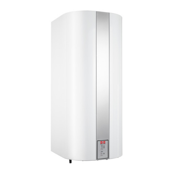
Summary of Contents for Metro Therm 60
- Page 1 ELECTRICAL WATER HEATERS 78:013-1603 Manual Smart Control model 60, 110 and 160 Type 206 ECO, 211 ECO and 216 ECO...
- Page 2 Model 60 – 3 kW , Smart Control Type 206 ECO METRO-number: 112061003 VVS-number: 345181360 Model 110, Smart Control Type 211 ECO METRO-number: 112111003 VVS-number: 345181560 Model 160, Smart Control Type 216 ECO METRO-number: 112161003 VVS-number 345181760 Type 206 ECO...
-
Page 3: Table Of Contents
Table of Contents Transport Placement Drawing Hot Water Heater-setup Electrical Setup User’s Guide Maintenance Troubleshooting Warranty provisions Declaration of conformity... -
Page 4: Transport
Transport Immediately upon receipt, inspect the water heater for integrity and absence of damage. If there is damage, report it to the transport company immediately. The recipient is responsible for shipping unless otherwise agreed. -
Page 5: Placement
Please be aware that the wall must be able to support the weight of the tank including water. Water heater models 60, 110 and 160 – as an option – can be supplied with a stand and support plates with adjustable feet, making it possible to level the water heater on a solid, flat floor. -
Page 6: Drawing
Diagram Model 60-110-160 (type 206 ECO, 211 ECO, 216 ECO) Hot water output Cold water input Socket 3/4” with stopper (for circulation) Holes in mounting bracket CC measurements at mounting bracket Dimensions All measurements are shown in mm. Type No. -
Page 7: Hot Water Heater-Setup
1. Water input (cold) 3/4” shut off valve 2. Check valve (built-in) Salt based soft water may be used in a METRO THERM hot water tank. It would however be 3. Relief Valve a good idea to remove the anode before the tank is put into use, since otherwise the anode 4. - Page 8 Security system The safety valve shall be located in the water input near the tank and be readily accessible for testing and inspection. The connection pipe between the safety valve and the tank and the overflow from the safety valve must not be capable of being blocked. Opening min. 3/4”(Ø...
-
Page 9: Electrical Setup
Electrical Setup Note: Before power is The electrical installation should be performed only by a certified connected, the water electrician. heater must be filled with The water heater is constructed as class IP24 and must always have extra protection water. according to the LVD directive. - Page 10 Smart Control Electrical diagram 3 kW (1 kW) Type 206 ECO, 211 ECO og 216 ECO...
-
Page 11: User's Guide
User Guide Read this manual carefully before installation and before putting the water heater into service. Safety guidelines Installation, initial startup, and maintenance of this product may be performed only by autho- rised HVAC/electrical Installers who will be responsible for adherence to applicable standards and installation regulations. - Page 12 Start-up When switching on power to the water heater – at the switch in the fixed installation – the Smart Control will perform a short test; each of the seven LEDs will light up in turn. After a few seconds, the operational function ECO automatically switches on, using comfort level 2, and the water heater is put in operation.
- Page 13 (arrow down) until the LED next to the desired temperature level lights up. Temperature level no. 1 = 60°C should normally be used, as it minimizes limestone precipita- tion on the heating element and thus prolongs its life.
- Page 14 Note Pipes and faucets near the water heater can reach temperatures above 60˚C. The water heater is fitted with an Thermal Cut Out thermostat that interrupts the electric con- nection in case of excess temperature in the water heater. The Thermal Cut Out thermostat may be reconnected only by an authorized installer.
-
Page 15: Maintenance
Maintenance Exterior cleaning The water heater may be wiped down only with a damp cloth. Window and glass cleaning products can be used, but never scouring powder or varnish dissolving chemicals. Always read the instructions for the cleaning product. Relief Valve The pressure relief valve should be inspected at least twice per year. - Page 16 Inspection/replacement of the anode Must be performed only by a certified HVAC installer. The tank comes with a controllable magnesium anode. It is mounted in the bottom flange and is checked by disconnecting the tank connection and inserting a multimeter (see Figure 9). If the measured anode current is greater than 0.3 mA, the mass of the anode is large enough to protect the tank.
-
Page 17: Troubleshooting
Troubleshooting The table below can help identify and remedy problems. If the problem cannot be remedied using this table, contact an authorized HVAC/electrical installer. Error Cause Action No water flow Water supply disconnected Open ball valve - it may be on cold or hot water stream. -
Page 18: Warranty Provisions
The product must be placed so that it can be serviced without obstacles. If the product is positioned such that accessibility is dif- ficult, METRO THERM disavows any obligation in relation to additional costs that may arise. We refer to DS 439 §5.1 and §5.2. -
Page 19: Declaration Of Conformity
Declaration of conformity The declaration of conformity is available on our website: www.METROTHERM.dk... - Page 20 Get a 1-year additional warranty on your METRO product We offer a one-year additional warranty on your METRO product when you register the product and indicate the place and time of installation and the name of the installer company. Click on http://fqr.dk or scan the QR-code Enter product and installation information Once we have processed your information, you will receive an email confirming your additional warranty within a few days.


Need help?
Do you have a question about the 60 and is the answer not in the manual?
Questions and answers