Table of Contents
Advertisement
Quick Links
AUTHORISED SERVICE AGENTS:
CARBA-TEC Pty. Ltd.
40 Harries Road
Coorparoo, QLD 4151
Ph: (07) 3397 2577
Fax: (07) 3397 2785
CARBA-TEC (NSW) Pty. Ltd.
32 Percy Street
Auburn, NSW 2144
Ph: (02) 9649 5077
Fax: (02) 9649 7044
CARBA-TEC (MELB) Pty. Ltd.
80 - 82 Osborne Avenue
Springvale, VIC 3171
Ph: (03) 9558 4200
Fax: (03) 9558 5133
CARBA-TEC (WA)
151 Balcatta Road
Balcatta, WA 6021
Ph: (08) 9345 4522
Fax: (08) 9240 1014
CARBA-TEC NZ Ltd.
110 Harris Road
East Tamaki, Auckland
Ph: (09) 274 9454
Fax: (09) 274 9455
Advertisement
Table of Contents

Related Manuals for Carba-Tec CTJ-196

Summary of Contents for Carba-Tec CTJ-196
- Page 1 AUTHORISED SERVICE AGENTS: CARBA-TEC Pty. Ltd. 40 Harries Road Coorparoo, QLD 4151 Ph: (07) 3397 2577 Fax: (07) 3397 2785 CARBA-TEC (NSW) Pty. Ltd. 32 Percy Street Auburn, NSW 2144 Ph: (02) 9649 5077 Fax: (02) 9649 7044 CARBA-TEC (MELB) Pty. Ltd.
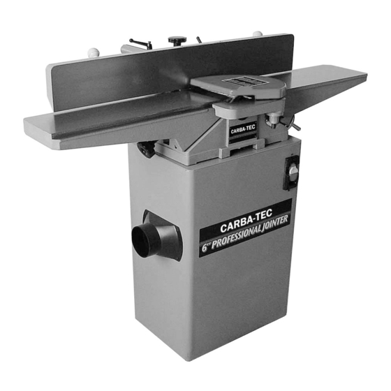
- Page 2 6” JOINTER MODEL CTJ-196 ®...
-
Page 3: Safety Warning
SAFETY WARNING: This list of do’s and do nots is not exhaustive and is not a substitute for common sense and best practices. Woodworking machines are potentially dangerous, it is important to observe all safety instructions while operating this machine. •... - Page 4 MOTOR PULLEY ASSEMBLY Fix the motor pulley Fig. 1 (A) onto the motor shaft mak- ing sure the hub of the pulley is facing out. Insert key into the keyway of the pulley and motor shaft. Make sure you tighten the set screw Fig. 1 (C) with the allen wrench supplied.
- Page 5 FENCE The fence is totally adjustable, and can move right across the table or tilt to 45 degrees. To move fence loosen the locking handle Fig. 7 (A) and turn the knob Fig. 7 (B) until fence is at desired loca- tion, tighten locking handle.
-
Page 6: Infeed Table
TABLE ADJUSTMENTS. INFEED TABLE The infeed table adjustment determines the depth of cut, by raising or lowering the table in relation to the cut- terhead. The lower the infeed table the larger the cut. Loosen the table lock handle Fig. 8 (A) at the back of the machine and raise the table by releasing the lever Fig. -
Page 7: Knife Setting
KNIFE SETTING The 3 blades in your jointer are factory set, and there- fore should already be set to the right height and parral- lel to the cutterhead. If for some reason you need to adjust the blades These are the steps to follow. Disconnect machine from power source. -
Page 8: Cutterhead Guard
CUTTERHEAD GUARD It it essential that the jointer is not operated without the cutterhead guard. 1. Insert post Fig. 19 (A) through the hole in the infeed table making sure that the spring assembly in the knob Fig. 19 (C) engages into the slot at the bottom of the post Fig. - Page 9 PLANING OR SURFACING FACE Surface the widest face first to establish one, totally straight face. This then becomes the reference which goes against the fence allowing squaring of the edge of the board. Always use a push block when planing or surfacing. Fig.
- Page 15 ALL ELECTRICAL WORK SHOULD BE UNDERTAKEN BY A LICENSED ELECTRICAL CONTRACTOR.
- Page 16 NOTES...
Need help?
Do you have a question about the CTJ-196 and is the answer not in the manual?
Questions and answers