Table of Contents
Advertisement
Quick Links
Z
Dygi
one
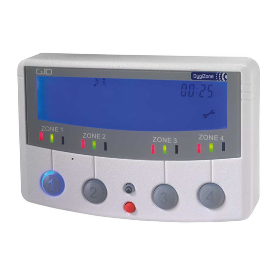
GJD910 Advanced Multi-function, 4 zone, security lighting
controller and enunciator
INTRODUCTION
The DygiZone 4 zone security lighting controller works in
conjunction with GJD's 4 Zone Expansion Unit and range
of external detectors.
PACKAGE CONTENTS
1 x DygiZone 4 zone security lighting controller
2 x fixing screws
2 x wall plugs
1 x installation guide
POWERING UP THE DYGIZONE
After powering up the DygiZone controller with the battery
removed:
•
Each zone's status LEDs (red, yellow and green)
and blue zone buttons will flash
•
All LCDs icons will display on the screen
When installation is completed removing the backup
battery tab will enable the clock to keep running in the
event of power loss
NOTE: Press any button to clear the display.
Alternatively, the display will clear automatically after
1 minute.
When the display clears, and if nothing is activated:
•
The LCD displays the clock time (automatically
defaults to 00:00 if the battery is not connected)
•
The symbol M appears on the DygiZone which is
configured as the master controller.
Note: The letter M does not appear when setting up a
DygiZone as a slave controller.
•
Each zone's status LEDs will display the zone's
current programme state.
Note: The factory default setting is audible and
automatic for all active zones (red and green status
LEDs illuminated).
ZONE INDICATOR ICONS
For each of the 4 zones there are a set of sub-zone icons
that appear above the respective zone's status LEDs.
Note: These icons will not be displayed until a detector
on the system has triggered.
When a detector connected to the A1, A2 or A3 input of the
Expansion Unit is triggered:
•
The LCD will display the numbers 1,2 and 3 above
the respective zone number.
•
A circle will appear around the number that
corresponds to the detector that has been triggered.
•
The corresponding zone's button will illuminate.
Note: The numbers 1, 2 and 3 correspond to the
Expansion unit inputs A1, A2 and A3 respectively.
Upon activation the circle will flash for 8 seconds and then
will remain visible for a time duration equal to the setting
of TIME MINS in the engineer programming. The numbers
1, 2 and 3 will also be visible for this time but will not flash.
Once this time has elapsed, all the icons will clear from the
LCD.
ZONE MODES & STATUS INDICATORS
Audible Mode: Beep or voice mode is activated and will
sound on detector activation.
Status Icon: Musical note icon for either voice
or beep more. The microphone icon is only
visible if voice mode is selected.
Status LED: Red, constantly lit.
Automatic Mode: Works in conjunction with the photocells
in the detectors. The external security lights will only be
activated if it is dark, thereby saving energy.
Status Icon: Stick figure icon
Status LED: Green, constantly lit LED
indicates mode selected.
Yellow LED illuminates when the external
lighting is activated.
Manual Override Mode: The external security light will
now remain on irrespective of detector status - useful for
barbecues or when working outside in the dark for long
periods.
Status Icon: Light bulb icon
Status LED: Yellow, lit during light activation
period.
Time Mode: External security lights will be illuminated as
per the TIME 1 or Timer 2 options.
Status Icon: Light bulb icon
Status LED: Yellow, lit during light activation
period.
Note: Zone status icons are only visible when the
respective zone button is pushed. The icons are
located in the top-centre of the LCD display.
INDIVIDUALLY SETTING ZONES
Each zone can be individually configured from the keypad
by cycling through the available modes.
The configuration process is as follows:
•
Press the button for zone you would like to configure.
The zone's status LEDs and icons will be displayed.
•
Press the button again to cycle through the different
modes available until the desired mode is reached.
Advertisement
Table of Contents

Related Manuals for GJD DygiZone


Summary of Contents for GJD DygiZone
- Page 1 INTRODUCTION • The corresponding zone’s button will illuminate. The DygiZone 4 zone security lighting controller works in Note: The numbers 1, 2 and 3 correspond to the conjunction with GJD’s 4 Zone Expansion Unit and range Expansion unit inputs A1, A2 and A3 respectively.
- Page 2 RECORDING A VOICE MESSAGE Press and hold the red button until the microphone If buttons are pressed for 30 seconds the DygiZone will symbol appears on the LCD. automatically exit the programming mode. Press the required zone button once and then release.
- Page 3 The number of times a detector must trigger (pulse count) before the DygiZone reacts is selected by adjusting the Note 2: Any zone times being used will display the time setting of PULSE in the engineer programming. This can in the selected format.
- Page 4 Repeat steps 3 & 4 for the T1 OFF time and again for the T2 ON & OFF times if required. It is recommended that the DygiZone which will be used Press any zone button to exit the programming. the most should be configured as the Master.
- Page 6 4 ZONE EXPANSION UNIT WIRING DIAGRAM...
- Page 7 +44 (0) 1706 363 998 Unit 2 Birch Business Park, Whittle Lane, Heywood, Greater Manchester, OL10 2SX,...
Need help?
Do you have a question about the DygiZone and is the answer not in the manual?
Questions and answers
i can't re-adjust the pre-set light on/off times for the individual zones
To re-adjust the pre-set light on/off times for individual zones on the GJD DygiZone:
1. Press the zone button for the zone you want to adjust.
2. When the hour starts flashing, enter the desired hour using the buttons.
3. Press the red button to confirm the hour.
4. The minutes will then flash; enter the desired minutes.
5. Press the red button again to confirm the time.
6. Repeat the process for T1 OFF time and for the T2 timer if needed.
If timers are not required, set both ON and OFF times to 01:00.
This answer is automatically generated