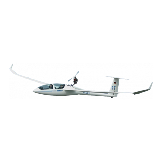
DG Flugzeugbau DG-1000T Maintenance Manual
Hide thumbs
Also See for DG-1000T:
- Repair manual (16 pages) ,
- Maintenance manual (152 pages) ,
- Flight manual (130 pages)

Related Manuals for DG Flugzeugbau DG-1000T


Summary of Contents for DG Flugzeugbau DG-1000T
- Page 2 Maintenance Manual DG-1000T Maintenance Manual DG-1000T List of effective pages (continued) List of effective pages (continued) Section page issued replaced/ replaced/ replaced/ diagram issued replaced/ replaced/ replaced/ 1.26 " May 2004 " 1.27 Nov. 2001 1.28 " June 2005 1.26 "...
- Page 3 Maintenance Manual DG-1000T Maintenance Manual DG-1000T 1.6 Undercarriage diagrams 1.6.1 Main wheel (Version without nose wheel) Elevator control, trim 1.6.1.1 Undercarriage control circuit Rudder control see diagram 12 and 7 (inside landing gear box) Aileron and spoiler controls in the fuselage Aileron and spoiler controls in the wings In the retracted position the undercarriage is locked by an over centre device.
- Page 4 Maintenance Manual DG-1000T Maintenance Manual DG-1000T 1.8.2 Fin tank c) With TN1000/13 executed, standard from ser. no. 10-133 on:: Adjust the stop bolt in part 10FW74 so that dimension a will be between 14,5 and The fin ballast tank is constructed as integral tank.
- Page 5 Maintenance Manual DG-1000T Maintenance Manual DG-1000T 1.12.6 Starter: 2 Inspections Electric starter motor, type see section 8.1. 2.1 Daily inspection 1.12.7 Ignition system: see flight manual section 4.3 spark plugs; Electrode gap 0.5 mm (0.02 in.), type see section 8.1.
- Page 6 Maintenance Manual DG-1000T Maintenance Manual DG-1000T C Removal of the lower landing gear fork 10Fw11/1 F Removal of the front fork 10Fw10/1 Remove the main wheel see A. 1. Remove the baggage compartment floor and the rear cover of the Retract the landing gear.
- Page 7 Maintenance Manual DG-1000T H Removal of the front upper fork 10Fw13/1 1. Remove the main wheel see A. 2. Retract the landing gear. Warning: The landing gear will retract by itself when unlocked by the force of the gas spring! 3.
- Page 8 Landing gear positive locking device diagram17 issued February 2008 TN1000/13 installation of the notch (LG extended) to 10FW12/2 direction of flight Installation of the locking catch. View LG retracted, locking catch not engaged...
- Page 9 Enclosure 3 for maintenance manual DG-1000T Optional throttle handle in the rear cockpit TN1000/15 Service Instructions Part designations see MM diagram 19 and sketches below I. Bleeding the hydraulic system Necessary material: • Hydraulic fluid: Magura Blood Hydraulic Mineral Oil (don’t use brake fluid) Necessary tools: •...
- Page 10 Enclosure 3 for maintenance manual DG-1000T Securing the terminal nipples Use lock wire with min. 0.8 mm diameter. The lock wire is necessary to prevent the connection from inadvertent opening. 12. Reinstall all parts. The clamp at the front cylinder must contact the lower flange of the cylinder.
Need help?
Do you have a question about the DG-1000T and is the answer not in the manual?
Questions and answers