Table of Contents
Advertisement
Available languages
Available languages
Quick Links
Installation Guide
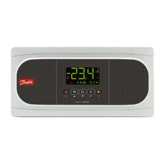
Temperature controller for walk-in coolers
and freezers, Type AK-RC 251
EN : Temperature controller for walk-in coolers and freezers
ES : Controlador de temperatura para cuartos fríos y congeladores
Type AK-RC 251
Warnings
• Using the unit without observing the manufacturer's instructions may alter the appliance's safety requirements. Only NTC probes
supplied by Danfoss should be used for the unit to operate correctly.
• From -40 – +68 °F, if the NTC probe is extended to 3,280 ft with at least 20AWG cable, the maximum deviation will be 0.45 °F.
• It should be installed in a place protected from vibrations, water and corrosive gases, where the ambient temperature does not
exceed the value indicated in the technical data.
• For the reading to be correct, the probe should be used in a place without heat influences apart from the temperature you want to
measure or control.
• IP65 protection degree is only valid with the protection cover closed.
• IP65 protection degree is only valid if the cables enter the device using electrical conduit + gland with IP65 or above. The size of the
glands should be suitable for the diameter of the conduit used.
• Do not spray the unit directly with high-pressure hoses, as this could cause damage.
IMPORTANT:
• Before starting the installation, you must take the advice of local regulations in force.
• The AUXILIARY relays are programmable, and their operation depends on the configuration.
• The function of the digital inputs depends on the configuration.
• The recommended currents and powers are the maximum working currents and powers.
Wiring
Always disconnect the power supply to do the wiring.
The probes and their cables should NEVER be installed in a conduit together with power, control or power supply cables.
For disconnection, the power supply circuit must be equipped with a switch of at least 2 A, 230 V, located near the device. The power
supply cable will be H05VV-F or NYM 1x16/3. The section to be used as wire rated according to local regulations but must never be
less than 14AWG.
Cables for relay or contactor outputs should use 14AWG, allow working temperatures equal to or over 158 °F and be installed with as
few bends as possible.
The 120/230 V~ wiring must be kept clear of any other external element.
The wiring to be done depends on the type of installation. Use the appropriate diagram based on the option selected in the
wizard. Check the available options on the diagrams included in the controller's packaging.
Wizard refers to a built in tool to guide the user through the set up process.
Maintenance
• Clean the surface of the unit with a soft cloth, water and soap.
• Do not use abrasive detergents, gasoline, alcohol or solvents, as this might damage the unit.
© Danfoss | DCS (vt) | 2021.02
ENGLISH
080R9291
AN36292867744601-000101
AN36292867744601-000101 | 1
Advertisement
Table of Contents

Subscribe to Our Youtube Channel
Related Manuals for Danfoss Optyma AK-RC 251


Summary of Contents for Danfoss Optyma AK-RC 251
- Page 1 • Using the unit without observing the manufacturer's instructions may alter the appliance's safety requirements. Only NTC probes supplied by Danfoss should be used for the unit to operate correctly. • From -40 – +68 °F, if the NTC probe is extended to 3,280 ft with at least 20AWG cable, the maximum deviation will be 0.45 °F.
- Page 2 If the temperature regulation cannot be instantly stopped due to its configuration, a controlled stop process starts and the icon flashes. To stop the controlled stop process and force the step to Stand-by, press the Stand-by key again for 3 seconds. 2 | AN36292867744601-000101 © Danfoss | DCS (vt) | 2021.02...
-
Page 3: Initial Configuration
2=Hot gas Type of defrost 3=Reversal of cycle Status of the fans during the defrost 0=Shut down 1=Running For more details, full User Manual and other information, scan the QR code. © Danfoss | DCS (vt) | 2021.02 AN36292867744601-000101 | 3... -
Page 4: Regulation And Control
Stop fans and compressor on opening door 0=No, 1=Yes Start-up delay for fans and compressor with door open Min. Probe 3 calibration (Offset) ºF -36.0 36.0 Exit to level 1 4 | AN36292867744601-000101 © Danfoss | DCS (vt) | 2021.02... - Page 5 0= Relay ON in alarm (OFF without alarm); 1= Relay OFF in alarm (ON without alarm) Differential of temperature alarms (A1 and A2) ºF Delay of open door alarm (If I10 or I20=1) Min. Exit to level 1 © Danfoss | DCS (vt) | 2021.02 AN36292867744601-000101 | 5...
-
Page 6: Basic Configuration
HACCP alarm Level 1 Level 2 Description Values Min. Def. Max. Maximum temperature of HACCP alarm ºF Maximum permitted time for activation of the HACCP alarm (0=Disabled) Exit to level 1 6 | AN36292867744601-000101 © Danfoss | DCS (vt) | 2021.02... - Page 7 Shown sequentially with the temperature: The controller is in demo mode, the configuration has not been S1 - S2 made. A: Activates the acoustic alarm R: Activates the alarm relay © Danfoss | DCS (vt) | 2021.02 AN36292867744601-000101 | 7...
- Page 8 Code no. 3.5 m, NTC 10K Sensor Thermo plastic rubber probe 084N3210 8.5 m, NTC 10K sensor Thermo plastic rubber probe 084N3208 1.5 m, NTC 10K sensor Stainless steel probe 084N3200 8 | AN36292867744601-000101 © Danfoss | DCS (vt) | 2021.02...
-
Page 9: Mantenimiento
• Utilizar el controlador sin respetar las instrucciones del fabricante, puede alterar los requisitos de seguridad del enfriador. Para el funcionamiento correcto del mismo sólo deberán utilizarse sensores de temperatura tipo NTC suministrados por Danfoss. • Entre –40 ºF y +68 ºF, si el sensor de temperatura NTC es colocado hasta 1.000m de distancia con cable de calibre mínimo 20AWG, la desviación de temperatura máxima esperada será... - Page 10 Pump Down, se inicia un proceso de paro controlado y el icono parpadea. Para detener el proceso de paro controlado y forzar el paso a Stand-by, presionar la tecla Stand-by nuevamente durante 3 segundos. 10 | AN36292867744601-000101 © Danfoss | DCS (vt) | 2021.02...
- Page 11 3=Ciclo invertido Estado de los abanicos durante el 0=Apagados 1=Encendidos deshielo Para más información, incluyendo el Manual de Usuario, use el código QR para acceder a la página de soporte. © Danfoss | DCS (vt) | 2021.02 AN36292867744601-000101 | 11...
- Page 12 Detener ventiladores y compresor al abrir puerta, 0=No, 1=Si Retraso de arranque de ventiladores y compresor con puerta abierta Min. Calibración del sensor 3 (Offset) ºF -36.0 36.0 Salida a nivel 1 12 | AN36292867744601-000101 © Danfoss | DCS (vt) | 2021.02...
- Page 13 0= Relevador ON en alarma (OFF sin alarma); 1= Relevador OFF en alarma (ON sin alarma) Diferencial de alarmas de temperatura (A1 y A2) ºF Retraso de alarma de puerta abierta (Si I10 ó I20=1) Min. Salida a nivel 1 © Danfoss | DCS (vt) | 2021.02 AN36292867744601-000101 | 13...
-
Page 14: Configuración Básica
Alarma HACCP Nivel 1 Nivel 2 Descripción Valores Min. Def. Max. Temperatura máxima para alarma HACCP ºF Tiempo máximo permitido para activación de alarma HACCP (0=Deshabilitada) Salida a nivel 1 14 | AN36292867744601-000101 © Danfoss | DCS (vt) | 2021.02... - Page 15 Mostrados de forma secuencial con la temperatura: El controlador está en modo demo, la configuración no se S1 - S2 ha realizado A: Activa la alarma acústica R: Activa el relé de alarma © Danfoss | DCS (vt) | 2021.02 AN36292867744601-000101 | 15...
- Page 16 3.5 m, NTC 10K Sensor Sensor de Goma termoplástica 084N3210 8.5 m, NTC 10K sensor Sensor de Goma termoplástica 084N3208 1.5 m, NTC 10K sensor Sensor de acero inoxidable 084N3200 16 | AN36292867744601-000101 © Danfoss | DCS (vt) | 2021.02...
Need help?
Do you have a question about the Optyma AK-RC 251 and is the answer not in the manual?
Questions and answers