Advertisement
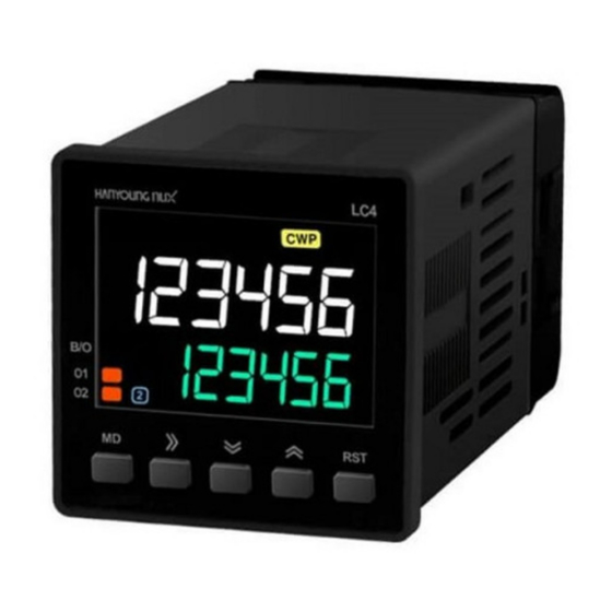
LC series
LCD Counter & Timer
USER'S MANUAL
Thank you for purchasing Hanyoung Nux products. Please read the instruction manual
carefully before using this product, and use the product correctly. Also, please keep this
manual where you can view it any time.
Safety information
Please read the safety information carefully before the use, and use the product correctly. The alerts
declared in the manual are classified into Danger, Warning and Caution according to their importance
DANGER
Indicates an imminently hazardous situation which, if not avoided, will result in death or serious injury
WARNING
Indicates a potentially hazardous situation which, if not avoided, could result in death or serious injury
Indicates a potentially hazardous situation which, if not avoided, may result in minor injury or
CAUTION
property damage
DANGER
• The input/output terminals are subject to electric shock risk. Never let the
input/output terminals come in contact with your body or conductive substances.
WARNING
• Any use of the product other than those specified by the manufacturer may result in
personal injury or property damage.
• If there is a possibility that a malfunction or abnormality of this product may lead to a
serious accident to the system, install an appropriate protection circuit on the outside.
• Since this product is not equipped with a power switch and fuse,
install them separately on the outside (fuse rating: 250 VAC 0.5 A).
• Please supply the rated power voltage, in order to prevent product breakdowns or malfunctions.
• To prevent electric shocks and malfunctions, do not supply the power until the wiring is completed.
• The product does not have an explosion-proof structure, so avoid using it in places with
flammable or explosive gases.
• Never disassemble, modify, process, improve or repair this product, as it may cause
abnormal operations, electric shocks or fires.
• Please disassemble the product after turning OFF the power. Failure to do so may result
in electric shocks, product abnormal operations or malfunctions.
• Please use this product after installing it to a panel, because there is a risk of electric shock.
CAUTION
• The contents of this manual may be changed without prior notification.
• Please make sure that the product specifications are the same as you ordered.
• Please make sure that there are no damages or product abnormalities occurred during shipment.
• Please use the product in places where corrosive gases (especially harmful gases,
ammonia, etc.) and flammable gases are not generated.
• Please use the product in places where vibrations and impacts are not applied directly.
• Please use the product in places without liquids, oils, chemicals, steam, dust, salt, iron, etc.
• Please do not wipe the product with organic solvents such as alcohol, benzene, etc.
(use neutral detergents).
• Please avoid places where large inductive interference, static electricity,
magnetic noise are generated.
• Please avoid places with heat accumulation caused by direct sunlight, radiations, etc.
• Please use the product in places with elevation below 2000 m.
• When water enters, short circuit or fire may occur, so please inspect the product carefully.
• When there is a lot of noise from the power, we recommend to use insulation
transformer and noise filter. Please install the noise filter to a grounded panel, etc. and
make the wiring of noise filter output and power supply terminal as short as possible.
• Tightly twisting the power cables is effective against noise.
• Do not wire anything to unused terminals.
• Please wire correctly, after checking the polarity of the terminals.
• When you install this product to a panel,
please use switches or circuit breakers compliant with IEC60947-1 or IEC60947-3.
• Please install switches or circuit breakers at close distance for user convenience.
• We recommend regular maintenance for the continuous safe use of this product.
• Some components of this product may have a lifespan or deteriorate over time.
• The warranty period of this product, is 1 year, including its accessories,
under normal conditions of use.
• The preparation period of the contact output is required during power supply.
If used as a signal to external interlock circuit, etc. please use a delay relay together.
Model code
Model
Code
LC
□- □
□
□
□
3
4
Dimensions
6
7
Settings
P
4
Display digits
6
1
Control output
2
Sub output
Power voltage
Content
□ LCD Counter & Timer
96(W) × 48(H) mm
48(W) × 48(H) mm
72(W) × 36(H) mm
72(W) × 72(H) mm
Preset Counter & Timer
4 digits (9999) ※LC4 only
6 digits (999999)
1-stage output
2-stage output
N
No sub output
C
RS485 (MODBUS-RTU)
A
100 - 240 V a.c. 50/60 ㎐
D
24 - 48 V a.c. 50/60 Hz or 24 - 48 V d.c.
HANYOUNGNUX CO.,LTD
HEAD OFFICE/
28, Gilpa-ro 71beon-gil, Michuhol-gu, Incheon, Korea
FACTORY
TEL : +82-32-876-4697 FAX : +82-32-876-4696
http://www.hanyoungnux.com
Specifications
Model
LC3
AC
100 - 240 V a.c. 50/60 Hz (voltage luctuation rate: ±10%)
Power
voltage
DC 24 - 48 V a.c. 50/60 Hz or 24 - 48 V d.c. (voltage luctuation rate: ±10%)
AC ▪2-stage setting type: max. 12VA ▪1-stage setting type: max. 11VA
Power
consumption
DC ▪2-stage setting type: max. 6W ▪1-stage setting type: max. 5W
Counting unit
(14.5 mm),
Character height
Setting unit
(10 mm)
Max counting speed
Power outage
compensation
▪Selection of input method by external switch
(voltage input / non-voltage input)
▪Counter: composed of CP1, CP2, RESET, BATCH -RESET
▪Timer: composed of START, INHIBIT, RESET
Input
▪Voltage input: HIGH level (5 - 30 V d.c.),
LOW level (0 - 2 V d.c.),input resistance (about 4.5 kΩ)
▪ Non-voltage input: impedance during short-circuit (max. 1 kΩ),
residual voltage during short-circuit (max. 2 V d.c.)
Minimum input
signal time
External power
supply
ONE SHOT output
1-stage
OUT (SPDT, 1c)
2-stage
OUT1 (SPST, 1a), OUT2 (SPDT, 1c) * OUT2 of LC6-P62C: SPST coniguration
▪ SPDT: NC (250 V a.c. 2 A), NO (250 V a.c. 5 A), resistive load
capacity
1-stage
* LC4-P61C / P41C models NPN 1 circuit coniguration
NPN 2 circuits
2-stage
(OUT1,OUT2)
capacity
Timer operation error Power start: max. ±0.01 % ±0.05 sec Reset start: max. ±0.01 % ±0.03 sec
protocol
method
synchronism
speed
efective distance
max. connections
response
waiting time
START BIT
STOP BIT
DATA BIT
PARITY BIT
Insulation resistance Min. 100 MΩ (500 V d.c.) conductive part terminal - unilled metal
Dielectric strength
2000 V a.c. 60 Hz for 1 minute (diferent live part terminals)
Noise immunity
Square-wave noise by noise simulator ±2000 V (pulse width 1 ㎲)
Shock resistance
300 m/s² (30G), 3 times each in X, Y and Z direction
Vibration durability
10 - 55 ㎐, single amplitude 0.5 ㎜, 3-axis each direction, 2 h
electrical
Relay
life
mechanical
Degree of protection
Storage temperature
Ambient temperature
-10 ~ 55 ℃, 35 ~ 85 % RH (without condensation)
& humidity
Weight(g)
196
1
MD0901E210115
LC4
LC6
▪6-digit :
Counting unit
(10.8 mm),
Setting unit
Counting unit
(8 mm)
(10.5 mm),
▪4-digit :
Setting unit
Counting unit
(6.7 mm)
(14 mm),
Setting unit
(8.5 mm)
1 cps / 30 cps / 1 Kcps / 10 Kcps
10 years (using non-volatile memory)
1 ms / 20 ms (START, INHIBIT, RESET inputs)
Max. 12 V d.c. 100 mA
0.01 ~ 99.99 SEC
OUT (SPST, 1a) OUT (SPDT, 1c)
▪ SPST: 250 V a.c. 5 A, resistive load
NPN 2 circuits (OUT, BAT.O),
-
Open collector, max. 30 V d.c. 100 ㎃
Modbus RTU
RS485 (2-wire half-duplex)
Asynchronous
2,400 / 4,800 / 9,600 / 19,200 / 38,400 bps
Max. within 800 m
31 (address : 1 ~ 127)
5 ~ 99 ms
1 bit (ixed)
1 bit (ixed)
8 bit
None / Odd / Even
Min. 50,000 times
Min. 10,000,000 times
IP66 (product front)
-25 ~ 65 ℃ (without condensation)
140
143
LC7
Counting unit
(17.2 mm),
Setting unit
(12.5 mm)
NPN 2 circuits
(OUT1,OUT2)
222
Advertisement
Table of Contents

Related Manuals for HANYOUNG NUX LC Series


Summary of Contents for HANYOUNG NUX LC Series
- Page 1 LCD Counter & Timer USER'S MANUAL HANYOUNGNUX CO.,LTD Thank you for purchasing Hanyoung Nux products. Please read the instruction manual HEAD OFFICE/ 28, Gilpa-ro 71beon-gil, Michuhol-gu, Incheon, Korea carefully before using this product, and use the product correctly. Also, please keep this...
-
Page 2: Power Supply
Maximum counting speed Function mode configuration The maximum counting speed is the maximum response speed when you input the duty ratio (ON / OFF ratio) of the count input signal as 1: 1. ① Even when the input signal is below the maximum counting speed, it may not be counted if the ON and OFF times are less than the speciied minimum signal width. -
Page 3: Input/Output Connection
Counter input actions Input/output connection █ Input logic selection (voltage / non-voltage) A shall be above the minimum signal width, and B above 1/2 of the minimum signal width 1. After turning off the power, check the NPN / PNP display on case top and Up - A inhibit input Down - A inhibit input operate the transfer switch. -
Page 4: Batch Counter
Counter output modes One shot output (0.01 s ~ 99.99 s) ※ In case of 1-stage model, it is operated as SET2 and OUT2. ※ Apply a reset signal to the front reset (RST) key or external RESET terminal. Self-holding output Self-holding output One shot output (0.01 s ~ 99.99 s) Input mode... - Page 5 View and change counter set value ● If you press in counter operation mode, SET1 or SET2 set value is displayed in SV display sequentially. ●To change the set value, select the SET1 or SET2 set value to change with , then press to enter set value change mode.
- Page 6 Timer output modes One shot output (0.01 s ~ 99.99 s) Self-holding Self-holding One shot output output output (0.01 s ~ 99.99 s) Output mode Operation description Output mode Operation description Power RUN - ON delay Signal START - ON delay1 •...
- Page 7 Twin timer output modes Operation Operation description Output mode Output mode description Power RUN - ON delay • OFF time (SET1) is displayed at the Power RUN - Flicker_P same time as power is on • While power is on, OUT1 output is •...
- Page 8 █ Batch timer set value and batch set value change operation mode digit shift (time value display mode) time value set value digit shift digit shift digit shift digit shift digit shift set value change mode set value save set value save set value save set value save set value save...
-
Page 9: Communication Configuration
Communication configuration COMMANDS 1. Func 01H (Read Coil Status) Terminal resistance Terminal resistance RS232C 120 Ω 120 Ω Query (Master) Start Addr No. of Points CRC16 Slave Func Addr High High High LC #31 1byte 1byte 1byte 1byte 1byte 1byte 1byte 1byte CV310 converter... - Page 10 6. Func 06H (Preset Single Register) Query (Master) Slave Register Addr Preset Data CRC16 Func Addr High High High 1byte 1byte 1byte 1byte 1byte 1byte 1byte 1byte Response (Slave) Slave Register Addr Preset Data CRC16 Func Addr High High High 1byte 1byte 1byte...
- Page 11 MAPPING TABLE 1. Func 01H/05H Mapping Table (output status / reset) 4. Func 03H/06H/10H Mapping Table (SV / counter / timer / communication settings) Output status / reset SV settings ADDR FUNC Function Setting range ADDR FUNC Function Setting range 00001 (0000) 01/05 Reset terminal input 0...
- Page 12 Timer settings ADDR FUNC Function Setting range twin timer counter 40101 (0064) 03/06/16 Operation mode 1 batch-counter 4 batch-timer timer u.01s d.01s u.1s d.1s 40102 (0065) 03/06/16 Range 40103 (0066) 03/06/16 Scale Decimal 1 Sexagesimal ※ Timer pond s.on1 sond s.int sofd s.flk...
- Page 13 Dimensions and panel cutouts [Unit: ㎜] █ LC3 ● Dimensions ● Panel cutout █ LC4 ● Dimensions ● Panel cutout █ LC6 ● Dimensions ● Panel cutout █ LC7 ● Dimensions ● Panel cutout...
-
Page 14: Connection Diagrams
Connection diagrams No sub output RS485 (MODBUS-RTU) Model 1-stage output 2-stage output 1-stage output 2-stage output ●LC3-P61N ●LC3-P62N ●LC3-P61C ●LC3-P62C ●LC4-P61N/P41N ●LC4-P62N/P42N ●LC4-P62C/P42C ●LC4-P61C/P41C ●LC6-P62N ●LC6-P61C ●LC6-P62C ●LC6-P61N ●LC7-P61N ●LC7-P62N ●LC7-P61C ●LC7-P62C...
Need help?
Do you have a question about the LC Series and is the answer not in the manual?
Questions and answers