Table of Contents
Advertisement
Quick Links
Advertisement
Table of Contents

Subscribe to Our Youtube Channel
Related Manuals for Panduit ATLONA AT-PS-POE

Summary of Contents for Panduit ATLONA AT-PS-POE
- Page 1 Power over Ethernet Mid-Span Power Supply Atlona Manuals AT-PS-POE Extenders...
- Page 2 Version Information Version Release Date Notes Dec 2020 New format AT-PS-POE...
- Page 3 Welcome to Atlona! Thank you for purchasing this Atlona product. We hope you enjoy it and will take a extra few moments to register your new purchase. Registration only takes a few minutes and protects this product against theft or loss. In addition, you will receive notifications of product updates and firmware.
- Page 4 Atlona, Inc. (“Atlona”) Limited Product Warranty Coverage Atlona warrants its products will substantially perform to their published specifications and will be free from defects in materials and workmanship under normal use, conditions and service. Under its Limited Product Warranty, Atlona, at its sole discretion, will either: •...
- Page 5 Atlona, Inc. (“Atlona”) Limited Product Warranty • Damage, deterioration or malfunction resulting from the installation or removal of this product from any installation, any unauthorized tampering with this product, any repairs attempted by anyone unauthorized by Atlona to make such repairs, or any other cause which does not relate directly to a defect in materials and/or workmanship of this product.
- Page 6 Safety and Certification 9. Do not defeat the safety purpose of a polarized CAUTION or grounding-type plug. A polarized plug has two RISK OF ELECTRIC SHOCK blades with one wider than the other. A grounding DO NOT OPEN type plug has two blades and a third grounding CAUTION: TO REDUCT THE RISK OF prong.
-
Page 7: Table Of Contents
Table of Contents Introduction Features Package Contents Panel Description Front Panel Rear Panel Installation External Power Supply Connection Instructions Connection Diagram Appendix Specifications AT-PS-POE... -
Page 8: Introduction
Introduction The Atlona AT-PS-POE is a 48 VDC mid-span power injector designed to send remote power to HDBaseT products that operate on IEEE 802.03af Power over Ethernet. When placed within an HDBaseT transmission line, it allows two PoE-powered products to work together. The power supply features two power switches to selectively send power up- or down-stream. -
Page 9: Panel Description
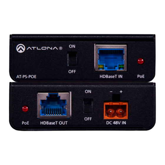
Panel Description Front Panel AT-PS-POE HDBaseT IN ON/OFF Toggles power transmission to the transmitter on and off. When set to the ON position, power will be supplied to the transmitter over the HDBaseT IN port. IMPORTANT: If the transmitter has power, then this switch must be set to the OFF position. HDBaseT OUT DC 48V IN HDBaseT IN... -
Page 10: Rear Panel
Panel Description Rear Panel AT-PS-POE HDBaseT IN HDBaseT OUT DC 48V IN This LED indicator is red when the ON/OFF switch is set to the ON position. In this state, power will be supplied to the transmitter over the HDBaseT IN port. HDBaseT OUT Connect a category cable (CAT-5e or better) from this port to the receiver. -
Page 11: Installation
Installation External Power Supply The AT-PS-POE is powered by the included 48 V / 0.83 A DC power supply. Insert the positive and negative leads, from the power supply, into the terminals of the 2-pin captive screw connector block, as shown. The orange 2-pin captive screw connector block is included. -
Page 12: Connection Instructions
Installation Connection Instructions 1. Connect a category cable (CAT-5e or better) from the HDBaseT IN port to the transmitter device. 2. Connect a category cable (CAT-5e or better) from the HDBaseT OUT port to the receiver device. 3. Connect the included 48 V / 0.83 A DC power supply to this port. Refer to External Power Supply (page 11) more information. -
Page 13: Connection Diagram
Installation Connection Diagram Laptop Laptop -T X 1 0 H V S -2 -H D L IN AT-HDVS-210H-TX-WP se T O FF PS -P A T- AT-PS-POE Projector with HDBaseT AT-PS-POE... -
Page 14: Appendix
Appendix Specifications Buttons and Indicators Switches: ON/OFF 2 – Slide switch Indicators: 1 – LED, red Connectors HDBaseT IN 1 – RJ45 HDBaseT OUT 1 – RJ45 DC 48V IN 1 – Euroblock, 2-pin Environmental Fahrenheit Celsius Operating Temperature +32 to +122 0 to +50 Storage Temperature -4 to +140... - Page 15 Toll free US International atlona.com 877.536.3976 41.43.508.4321 • • © 2020 Atlona Inc. All rights reserved. “Atlona” and the Atlona logo are registered trademarks of Atlona Inc. All other brand names and trademarks or registered trademarks are the property of their respective owners. Pricing, specifications and availability subject to change without notice.
Need help?
Do you have a question about the ATLONA AT-PS-POE and is the answer not in the manual?
Questions and answers