
Related Manuals for Emerson Dixell XR35CX - 110VAC


Summary of Contents for Emerson Dixell XR35CX - 110VAC
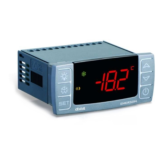
- Page 1 026-1203 Rev 3 03-FEB-2015 XR35CX Digital Controller for Medium Temperature Refrigeration Applications Installation and Operation Manual...
- Page 3 Emerson Climate Technologies Retail Solutions 1065 Big Shanty Rd., NW Suite 100 Kennesaw, GA 30144 USA Phone: 770-425-2724 Fax: 770-425-9319...
-
Page 5: Table Of Contents
Table of Contents 1 INTRODUCTION................................1 1.1. G ..............................1 ENERAL ARNING 2 OVERVIEW ................................... 1 2.1. G ..............................1 ENERAL ESCRIPTION 2.2. O ................................1 RDERING 3 CONTROLLING LOADS ............................2 3.1. C ................................2 OMPRESSOR 3.2. D ..................................2 EFROST 3.3. - Page 6 8.3. P 2F=PAL) ........................... 14 RESSURE WITCH 8.4. D ) ........................14 WITCH NPUT OR I 8.5. S EF)..........................14 TART EFROST OR I 8.6. S 2F=AUS) ......................14 WITCH THE UXILIARY ELAY 8.7. I 2F=H ) ..............14 NVERSION OF THE IND OF CTION EATING...
-
Page 7: Introduction
• Fit the probe where it is not accessible by the end user. The controller must not be opened. Device Emerson Dixell Code Name Code • In case of failure or faulty operation, send the... -
Page 8: Controlling Loads
Controlling Loads Other parameters are used to control defrost cy- cles: its maximum defrost duration (MdF) and two defrost modes: time or controlled by the evaporator’s probe (P2P). 3.3. Second Relay 3.1. Compressor Configuration (PAR. The regulation is performed according to the tem- oA1;... -
Page 9: Neutral Zone Regulation
3.3.5. Neutral Zone Regulation With oA1 = db, relay 1-7 can control a heater ele- ment to perform a neutral zone action. • oA1 cut in = SEt - Hy • oA1 cut out = SEt 3.3.6. Alarm Relay With oA1 = ALr, the relay 1-7 operates as an alarm relay. -
Page 10: Front Panel Commands
Front Panel To lock and unlock the keyboard. Commands To enter programming mode. To return to the room temperature dis- play. Table 4-1 - XR35CX Front Panel Keys and Functions 4.2. Use of LEDS Each LED function is described in Table 4-2: Mode Function Compressor enabled... -
Page 11: Max And Min Temperature Memorization
MAX and MIN Temperature Memorization 5.1. How to See the MIN Temperature 1. Press and release the DOWN arrow key. 2. The Lo message will be displayed followed by the minimum temperature recorded. 3. By pressing the DOWN arrow key again or by wait- ing 5 seconds, the normal display will be restored. -
Page 12: Main Functions
Main Functions Parameters for the list of parameters). Press the SET key to display its value. 3. Use the UP or DOWN arrow keys to change its val- 4. Press SET to store the new value and move to the following parameter. -
Page 13: How To Move A Parameter From The Hidden Menu To The First Level And Vice Versa
6.5.2. How to Move a Parameter 6.9. The Continuous Cycle from the Hidden Menu to the First Level and Vice Versa When defrost is not in progress, it can be activated Each parameter present in the Hidden Menu can by pressing the UP arrow key for about 3 seconds. be removed or put into THE FIRST LEVEL (user lev- The compressor operates to maintain the CCS set- el) by pressing SET + DOWN arrow keys. -
Page 14: Parameters
Parameters Code Parameter Function REGULATION Differential (0.1 to 25.5°C / 1 to 255°F) Intervention differential for setpoint. Compressor Cut IN is Setpoint + differential (Hy). Compressor Cut OUT is when the temperature reaches the setpoint. Minimum setpoint (-100°C to SEt/-148°F to SEt) Sets the minimum value for the setpoint. - Page 15 Code Parameter Function Compressor OFF time with faulty probe (0 to 255 min) Time during which the compressor is OFF in case of faulty thermostat probe. With CoF = 0, compressor is al- ways active. Type of action CL = cooling; Ht = heating DISPLAY Temperature measurement unit °C = Celsius;...
- Page 16 Code Parameter Function Maximum duration for defrost (0 to 255 min) When P2P = n, (not evaporator probe: timed defrost), it sets the defrost duration. When P2P = y (defrost end based on temperature), it sets the maximum duration for defrost. Start defrost delay (0 to 99 min) This is useful when different defrost start times are nec-...
- Page 17 Code Parameter Function Temperature alarms configuration (Ab; rE) Ab = Absolute temperature: alarm temperature is given by the ALL or ALU values; rE = Temperature alarms are referred to the setpoint. Temperature alarm is enabled when the temperature exceeds the SEt + ALU or SEt- ALL values.
- Page 18 Code Parameter Function Alarm relay silencing (with oA1 = ALr) n = silencing disabled: alarm relay stays ON until alarm condition lasts y = silencing enabled: alarm relay is switched OFF by pressing a key during an alarm Second relay configuration (1-7) dEF = defrost;...
- Page 19 Code Parameter Function First weekly holiday (Sun to not used) Sets the first day of the week which follows the holiday times. NOTE: Hd1 can be set also as not used value. Second weekly holiday (Sun to not used) Sets the second day of the week which follows the holi- day times.
-
Page 20: Digital Inputs
Digital Inputs Since the door is opened, after the delay time set through the parameter doA, the door alarm is enabled, the display shows the message dA and the regulation restarts is rtr = yES. The alarm stops as soon as the external digital input is disabled again. -
Page 21: On/Off Function
8.10. ON/OFF Function (i2F=onF) Switches the controller ON and OFF. 8.11. Digital Inputs Polarity The digital input polarity depends on the i1P and i2P parameters. • i1P or i2P CL: the input is activated by closing the contact. • i1P or i2P oP: the input is activated by opening the contact. -
Page 22: Rs485 Serial Line (For Monitoring Systems)
RS485 Serial Line 10 X-REP Output (for Monitoring (Optional) Systems) Optionally, an X-REP can be connected to the controller through the dedicated connector. The RS485 serial line allows you to connect the controller to a monitoring system MODBUS-RTU compatible, such as the X-WEB500/3000/300. Figure 10-1 - X-REP Output To connect the X-REP to the controller, the fol- lowing connectors must be used: CAB-51F(1m),... -
Page 23: Installation And Mounting
11 Installation and 12 Electrical Mounting Connections The controller comes with a screw terminal block to connect cables with a cross section up to 2.5 mm Before connecting cables, verify that the power sup- ply complies with the controller’s requirements. Sep- arate the probe cables from the power supply cables, from the outputs and the power connections. -
Page 24: How To Use The Hot Key
13 How to Use the NOTE: The Err message is displayed in case of Hot Key an error or failure in programming. In this case, turn the unit OFF and then ON if you want to restart the download or remove the Hot Key to abort the operation. -
Page 25: Alarm Signals
14 Alarm Signals Temperature alarms HA, LA, HA2, and LA2 au- tomatically stop as soon as the temperature returns to normal values. Alarms EA and CA (with i1F = bAL) recover as soon as the digital input is disabled. Message Cause Outputs Alarm CA (with i1F = PAL) recovers only by... -
Page 26: Specifications
15 Specifications Housing Self extinguishing ABS Case: Front: 32 mm x 74 mm, Depth: 60 mm Dimensions Panel Mount: 71 mm x 29 mm panel cut-out IP 20 Protection Frontal: IP65 Connections Screw terminal block ≤ 2.5 mm wiring 24VAC, ±10% Power Supply (depending on the model) 230VAC, ±10%, 50/60Hz 110VAC, ±10%, 50/60Hz... -
Page 27: Connections
16 Connections Figure 16-1 - XR35CX Connections • The X-REP output is optional. Other Messages Connections • 21... -
Page 28: E2 Modbus Network Wiring
17 E2 MODBUS Network Wiring • Connect the MODBUS Network to the RS485 Connector on the E2 PIB board (Belden 8641 recommended). • Note to wire the RS485 +/- polarity at the E2 in the reverse of the XR35CX devices. •... -
Page 29: Ect Modbus Networking To E2S
18 ECT MODBUS (P/N 637-4890) and configured in E2 General Ser- vices ( , Serial tab) to enable COM4 or Networking to an E2 Expansion COM Card (P/N 637-4871) to en- able COM6. Connect the MODBUS network cable to the three- terminal connector on the COM port you wish to as- sign as MODBUS. -
Page 30: E2 Setup Of Devices
An E2 has three COM ports that can be assigned COM port should be set to the same baud rate.) for MODBUS communication (COM2). COM ports • Data Size - Leave this field at the default value (8). can only be used for one function; in other words, if •... - Page 31 ter a new name for each device in the Name field. 8. When finished, press to return to the Net- work Setup menu, then press - Network Sum- mary (Figure 18-8). Locate the devices you set up, and look at each device’s status in the Status field. You will see one of the following messages: •...
-
Page 32: Wiring Types
18.4. Wiring Types 18.5. MODBUS Termination Blocks Retail Solutions specifies Belden #8761 shielded twisted pair cables for use as MODBUS wiring (or Belden #82761 and Belden #88761 for plenum instal- Because the XR35CX device has no on-board lations). means of termination, use the MODBUS termination block (P/N 535-2711) for termination that can be For MODBUS network wiring of XR35CX con- wired to the end of the cable segment using the three-... -
Page 33: Default Setting Values
19 Default Setting Values Label Name Range Value Level Setpoint LS to US Differential 0.1 to 25.5°C/ 1 to 255°F Minimum setpoint -100°C to SEt/-58°F to SEt -50.0 Maximum setpoint SEt to 110°C/ SEt to 230°F Thermostat probe calibration -12 to 12°C /-120 to 120°F Evaporator probe presence n = not present;... - Page 34 Label Name Range Value Level Draining time 0 to 120 min First defrost after start-up n = after IdF; y = immediate Defrost delay after fast freezing 0 to 23 hr and 50’ Kind of action for auxiliary relay CL; Ht Setpoint for auxiliary relay -100 to 110°C / -58 to 230°F Differential for auxiliary relay...
- Page 35 Label Name Range Value Level Digital input alarm delay (18-20) 0 to 255 min Door open alarm delay 0 to 255 min Number of activation of pressure switch 0 to 15 Compress status when open door no; Fan; CPr; F_C Regulation restart with door open alarm n –...
- Page 36 Label Name Range Value Level Fourth probe display Real set actual set Software release Map code Table 19-1 - Default Setting Values ( Only for XR35CX with X-REP output) 30 • XR35CX I&O Manual 026-1203 Rev 3 03-FEB-2015...
- Page 37 RS485-1B. For information on the maximum recommended number of XR, XM, and XEV devices for each network segment (load and bandwidth calculations), contact Emerson Retail Solutions Technical Support at 770-425- 2724. MODBUS Termination BlocksAppendix A - Alternate MODBUS COM Wiring Method for E2, XR, XM, and XEV Devic-...
- Page 38 Figure A -1 - MODBUS Com Wiring Diagram 32 • XR35CX I&O Manual 026-1203 Rev 3 03-FEB-2015...
- Page 40 Emerson Climate Technologies Retail Solutions, Inc. and/or its affiliates (collectively “Emerson”), reserves the right to modify the designs or specifications of such products at any time without notice. Emerson does not assume responsibility for the selection, use or maintenance of any product. Responsibility for proper selection, use and maintenance of any product remains solely with the purchaser and end-user.
Need help?
Do you have a question about the Dixell XR35CX - 110VAC and is the answer not in the manual?
Questions and answers