
Related Manuals for Rockwell Automation Allen-Bradley Guardmaster 442G MABH Series


Summary of Contents for Rockwell Automation Allen-Bradley Guardmaster 442G MABH Series
- Page 1 Multifunctional Access Box with CIP Safety over EtherNet/IP Catalog Numbers 442G-MABH-x, 442G-MABxB-Ux-x, 442G-MABE1 User Manual Original Instructions...
- Page 2 If this equipment is used in a manner not specified by the manufacturer, the protection provided by the equipment may be impaired. In no event will Rockwell Automation, Inc. be responsible or liable for indirect or consequential damages resulting from the use or application of this equipment.
-
Page 3: Table Of Contents
Reset Access Box to Factory Settings ......33 ControlFLASH Application Compatibility ......33 Rockwell Automation Publication 442G-UM002B-EN-P - August 2021... - Page 4 Index ............49 Rockwell Automation Publication 442G-UM002B-EN-P - August 2021...
-
Page 5: Preface
Provides an overview of the access box Read and understand this manual before using the described products. Consult your Allen-Bradley distributor or Rockwell Automation sales office if you have any questions or comments. Download firmware, associated files (such as AOP, EDS, and DTM), and access... -
Page 6: Additional Resources
Glossary of industrial automation terms and abbreviations Industrial Automation Wiring and Grounding Guidelines, publication 1770-4.1 Provides general guidelines for installing a Rockwell Automation industrial system. Product Certifications website, rok.auto/certifications. Provides declarations of conformity, certificates, and other certification details. (1) Devices manufactured with firmware revision 1.002 (check unit label) cannot be upgraded using ControlFLASH. Devices that are manufactured with firmware revision 1.005 and higher can be upgraded using ControlFlash. -
Page 7: Over Ethernet/Ip Overview
The GuardLocked input signal is turned on only when the locking bolt is sensed in its extended position in the lock module and the locking arm is in position (for example, the guard is closed and the bolt is both extended and locked). Rockwell Automation Publication 442G-UM002B-EN-P - August 2021... -
Page 8: Power To Release
ATTENTION: An unintended loss of power causes guard locking to be deactivated. Power to Lock versions should only be used for personal protection if minimum safe distance is provided in accordance with EN ISO 13855. Rockwell Automation Publication 442G-UM002B-EN-P - August 2021... -
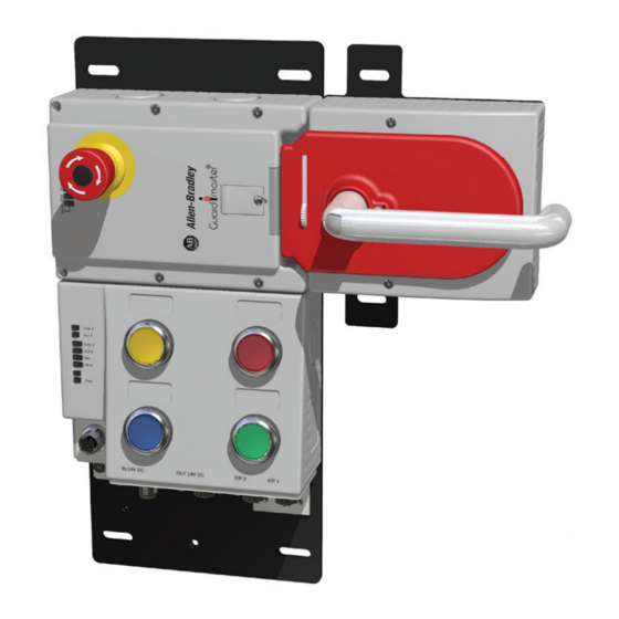
Page 9: Assembly Overview
Attaching an Enabling Switch (select models) Power Connectors Ethernet Connectors Figure 3 - Locking Module with Control Cover Status/Diagnostic Status Indicators 1 x Torx T8 Locking Arm Manual Release Cover Marking for Maximum Mounting Distance Rockwell Automation Publication 442G-UM002B-EN-P - August 2021... - Page 10 IMPORTANT The length of the actuation shaft (115 mm [4.53 in.]) is optimized for mounting on a 45 mm (1.77 in.) profile. An extended shaft is available (Cat. No. 442G-MABASHFT). See publication 442G-IN004 for instructions regarding mounting on smaller or larger profiles. Rockwell Automation Publication 442G-UM002B-EN-P - August 2021...
-
Page 11: Catalog Number Explanation
(see Clear Faults on page 39). ATTENTION: The locking screw must be screwed back in and sealed after assembly and after use of the manual release. Tightening torque is 0.5 N•m (4.42 lb•in). Rockwell Automation Publication 442G-UM002B-EN-P - August 2021... -
Page 12: Bolt Locking Mechanism
2 mm (0.08 in.) and the maximum diameter is 10 mm (0.39 in.) You can fit a maximum of three locks in an Roll-out 8 mm (0.31 in.) diameter. Mechanism Automatically Extending Mechanism Rockwell Automation Publication 442G-UM002B-EN-P - August 2021... -
Page 13: Mounting Plates
• 4X DIN 6797-JZ-D6,4 (lock washer) Escape Release Mounting Plate is supplied with the following hardware: • 4X DIN 7984-M6X8 (screw) • 4X DIN 433-6 NI (washer) • 4X DIN 6797-JZ-D6,4 (lock washer) Rockwell Automation Publication 442G-UM002B-EN-P - August 2021... -
Page 14: Typical Ethernet Configurations
The star structure consists of a number of modules that are connected to a central switch. Modules can be added or removed without affecting the rest of the network. Figure 10 - Example of Star Topology EtherNet/IP LNK1 LNK2 NET OK Rockwell Automation Publication 442G-UM002B-EN-P - August 2021... -
Page 15: Linear Topology
Sync or CIP Motion. To be used in linear topologies, where other nodes are using CIP Sync or CIP Motion, the access box must be connected at the end of the line. Figure 11 - Example of Linear Topology EtherNet/IP LNK1 LNK2 NET OK Rockwell Automation Publication 442G-UM002B-EN-P - August 2021... -
Page 16: Device Level Ring (Dlr) Topology
Sync or CIP Motion. To be used in linear topologies, where other nodes are using CIP Sync or CIP Motion, the access box must be connected at the end of the line. Figure 12 - Example Device Level Ring Topology EtherNet/IP LNK1 LNK2 NET OK Rockwell Automation Publication 442G-UM002B-EN-P - August 2021... -
Page 17: Standards
Guard locking is controlled with the Unlock output signal. Figure 13 - Control of Guard Locking Access Box Safety Output Signal (Unlock) (internal electronics) (For example, standstill monitor) Rockwell Automation Publication 442G-UM002B-EN-P - August 2021... - Page 18 General principles for design • EN ISO 14119, Safety of machinery. Interlocking modules that are associated with guards. Principles for design and selection • EN 60204-1, Safety of machinery. Electrical equipment of machines. General requirements. Rockwell Automation Publication 442G-UM002B-EN-P - August 2021...
-
Page 19: Safety Requirements For Integrated Safety Applications
PFD/PFH calculations, see the GuardLogix® safety reference manual for your controller. You must read, understand, and fulfill the requirements that are detailed in the safety reference manual before operating a safety system that uses this access box. Rockwell Automation Publication 442G-UM002B-EN-P - August 2021... - Page 20 Chapter 2 Safety Concept Notes: Rockwell Automation Publication 442G-UM002B-EN-P - August 2021...
-
Page 21: Set The Network Ip Address
If DHCP is not enabled, the access box uses the IP address (along with other TCP configurable parameters) stored in nonvolatile memory. Figure 16 on page 22 for an example of the network address DIP switches. Rockwell Automation Publication 442G-UM002B-EN-P - August 2021... -
Page 22: Set The Ip Address With A Bootp/Dhcp Server
If you use the BOOTP/DHCP server in an uplinked subnet where an enterprise DHCP server exists, an access box can get an address from the enterprise server before the Rockwell Automation utility sees the access box. If necessary, disconnect from the uplink to set the address and configure the access box to retain the static address before reconnecting to the uplink. - Page 23 The access box now uses the assigned configuration and no longer issues DHCP requests. IMPORTANT If you do not select Disable BOOTP/DHCP, then on a power cycle the access box clears the current IP configuration and begins sending DHCP requests again. Rockwell Automation Publication 442G-UM002B-EN-P - August 2021...
-
Page 24: Restore The Access Box To Dhcp Mode
7. Click Disable BOOTP/DHCP. Figure 18 - Disable DHCP IMPORTANT If you do not select Disable BOOTP/DHCP, then on a power cycle the access box clears the current IP configuration and begins sending DHCP requests again. Rockwell Automation Publication 442G-UM002B-EN-P - August 2021... -
Page 25: When The Ip Address Of The Access Box Is Unknown
An Add-on Profile (AOP) is available for the access box and can be used with RSLogix 5000® version 20 and higher. The profile can be downloaded from Box in the Logix Designer rok.auto/pcdc. Application Rockwell Automation Publication 442G-UM002B-EN-P - August 2021... -
Page 26: Add Access Box To The I/O Configuration Tree
At the bottom of a dialog box, choose Help for information about how to complete entries in the dialog box. At the bottom of a warning dialog box, choose Help to get information about that specific error. Rockwell Automation Publication 442G-UM002B-EN-P - August 2021... - Page 27 5. Click OK. IMPORTANT When NAT is used in a safety application with a GuardLogix® controller, the access box does not accept a safety connection unless the actual access box address is provided. Rockwell Automation Publication 442G-UM002B-EN-P - August 2021...
-
Page 28: Change The Access Box Definition
The catalog number in the Type field represents the catalog number of the access box being used. A picture of the device is displayed and can be used to confirm the module selection. Rockwell Automation Publication 442G-UM002B-EN-P - August 2021... -
Page 29: Configure The Safety Connection
10 ms. A smaller RPI consumes more network bandwidth.This can cause spurious trips because other access boxes cannot get access to the network. The selection of an appropriate RPI results in a system with maximum (best) performance. Rockwell Automation Publication 442G-UM002B-EN-P - August 2021... -
Page 30: Configuration Signature
IMPORTANT When replacing a device, if the replacement device was used previously and if the connection is local (as shown on the safety tab in RSLogix 5000), the device must first be reset to out-of-box condition. See publication 1756-UM020). Rockwell Automation Publication 442G-UM002B-EN-P - August 2021... - Page 31 2. Click Reset Ownership to re-establish the connection. 3. Click Yes to continue with ownership reset. 4. On the connection page, notice that the module is faulted (safety network number (SNN) not set, module-out-of-box). Rockwell Automation Publication 442G-UM002B-EN-P - August 2021...
- Page 32 Use the Multifunctional Access Box in an Integrated Safety Controller-based System 5. From the General tab, click Safety Network Number. The SNN dialog box appears. Enter the Number, Click Set, then click OK. 6. Select Yes to continue when the following warning appears. Rockwell Automation Publication 442G-UM002B-EN-P - August 2021...
-
Page 33: Reset Access Box To Factory Settings
Devices that are manufactured with firmware revision 1.002 (check unit label) cannot be upgraded with the ControlFLASH™ application. Devices that are Compatibility manufactured with firmware revision 1.005 and higher are compatible with the ControlFLASH application and can be upgraded with future firmware releases. Rockwell Automation Publication 442G-UM002B-EN-P - August 2021... - Page 34 Chapter 3 Use the Multifunctional Access Box in an Integrated Safety Controller-based System Notes: Rockwell Automation Publication 442G-UM002B-EN-P - August 2021...
- Page 35 Table 2 on page 36 for network status indicators. IP-Bit 4 IP-Bit 5 IP-Bit 3 IP-Bit 6 IP-Bit 2 IP-Bit 7 IP-Bit 1 DHCP IP-Bit 0 n.c. Table 3 on page 36 for DIP switch assignment. Rockwell Automation Publication 442G-UM002B-EN-P - August 2021...
- Page 36 Fixed part IP bit 3 The following applies: IP bit 2 OFF position = 0 Block 1 ON position = 1 IP bit 1 IP bit 0 Factory setting: all switches in OFF position. Rockwell Automation Publication 442G-UM002B-EN-P - August 2021...
- Page 37 (3) Latching fault; use corresponding output bit to reset; guard must be open. See Clear Faults on page Table 5 - Key to Symbols Status indicator not illuminated Status indicator flashes Status indicator illuminated Any state Rockwell Automation Publication 442G-UM002B-EN-P - August 2021...
- Page 38 This error indicates a problem with the power 2750 parameter assignment supply or a CIP Safety parameter assignment Disconnect and reconnect the power supply. None error error. (1) See Clear Faults on page Rockwell Automation Publication 442G-UM002B-EN-P - August 2021...
-
Page 39: Clear Faults
FaultCode, which deletes the previous one. The DiagnosticActive bit is set with each fault, but does not change state if the second fault occurs before the first fault is cleared. Rockwell Automation Publication 442G-UM002B-EN-P - August 2021... - Page 40 Chapter 4 Status and Troubleshooting Notes: Rockwell Automation Publication 442G-UM002B-EN-P - August 2021...
-
Page 41: Safety Ratings
(1) Refer to Electrical Connection—Power Supply Requirements in Installation Instructions, publication 442G-IN004. (2) The risk time is the maximum difference between the time the input status changes and the time the corresponding bit in the input assembly is turned on. Rockwell Automation Publication 442G-UM002B-EN-P - August 2021... -
Page 42: Environmental
• Handle assembly on mounting plate: 1.2 kg (2.6 lb) • Escape release: 500 g (17.6 oz) • Glass fiber reinforced plastic • Nickel-plated die-cast zinc Materials • Anodized aluminum handle • Stainless steel • Powder-coated sheet steel Rockwell Automation Publication 442G-UM002B-EN-P - August 2021... -
Page 43: Input Assemblies
Figure 22 on page 45). IMPORTANT Safety rated signals can be used in safety functions. Standard rated signals can be used in the safety task, but must not be relied on for safety functions. Rockwell Automation Publication 442G-UM002B-EN-P - August 2021... -
Page 44: Tag Definitions
Note: Logic is the same for both Power to Lock (PTL) and Power to Release (PTR) versions Unlock Command Fault — indicates a fault in the Unlock Command 1 = Fault UnlockCommandFault Standard BOOL 0 = OK, no fault Note: This tag rolls up into Diagnostic Active. Rockwell Automation Publication 442G-UM002B-EN-P - August 2021... - Page 45 EtherNet/IP I/O Assemblies Figure 21 - Right-hand System IN 24V DC OUT 24V DC LINK 2 LINK 1 Figure 22 - Left-hand System IN 24V DC OUT 24V DC LINK 2 LINK 1 Rockwell Automation Publication 442G-UM002B-EN-P - August 2021...
- Page 46 Appendix B EtherNet/IP I/O Assemblies Notes: Rockwell Automation Publication 442G-UM002B-EN-P - August 2021...
-
Page 47: Procedure
9 - Loosen the 3 mm setscrew. 10 - Reposition the door handle by CLOSED 90° in clockwise direction and fasten it again. Tighten setscrew to 2 N•m OPEN (17.7 lb•in). Final state after repositioning. Rockwell Automation Publication 442G-UM002B-EN-P - August 2021... - Page 48 Appendix C Change Actuation Direction of Handle Assembly Notes: Rockwell Automation Publication 442G-UM002B-EN-P - August 2021...
-
Page 49: Index
17 handle actuation direction configuration change 47 ethernet 14 handle assembly 10 configuration signature 30 hardware configure 26 mounting 13 Logix Designer application 25 safety connection 29 control guard locking 17 Rockwell Automation Publication 442G-UM002B-EN-P - August 2021... - Page 50 43 lock module 37 overview network 36 assembly 9 system product 7 left-hand 45 ownership right-hand 45 reset 30 definition 44 topology device-level ring (DLR) 16 linear 15 star 14 troubleshoot 35 Rockwell Automation Publication 442G-UM002B-EN-P - August 2021...
- Page 51 Multifunctional Access Box with CIP Safety over EtherNet/IP User Manual Rockwell Automation Publication 442G-UM002B-EN-P - August 2021...
- Page 52 At the end of life, this equipment should be collected separately from any unsorted municipal waste. Rockwell Automation maintains current product environmental information on its website at rok.auto/pec. Allen-Bradley, ControlFLASH, expanding human possibility, GuardLogix, Guardmaster, Rockwell Automation, RSLogix 5000, Studio 5000, and Studio 5000 Logix Designer are trademarks of Rockwell Automation, Inc.
Need help?
Do you have a question about the Allen-Bradley Guardmaster 442G MABH Series and is the answer not in the manual?
Questions and answers