Table of Contents
Advertisement
Quick Links
Installation Instructions
Original Instructions
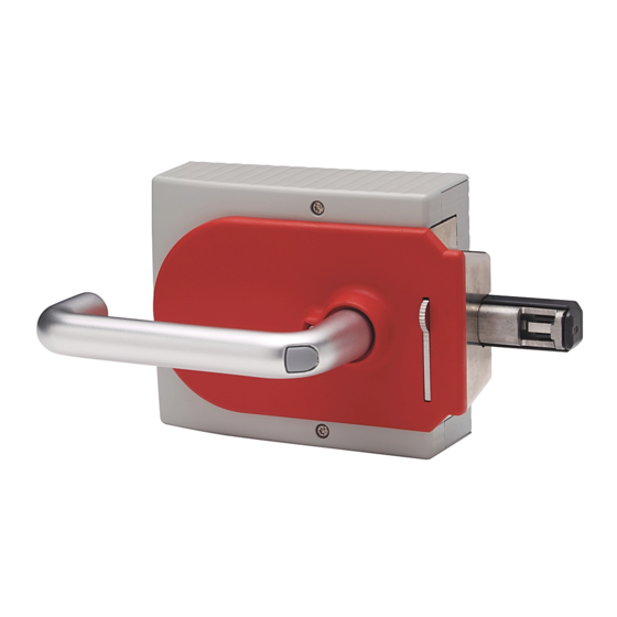
Multifunctional Access Box with CIP Safety over EtherNet/IP
Catalog Numbers 442G-MABH- , 442G-MAB B-U - , 442G-MABE1
ATTENTION: Read this document and the documents that are
listed in
Additional Resources on page 7
configuration, and operation of this equipment before you install,
configure, operate, or maintain this product. Users are required to
familiarize themselves with the installation and wiring
instructions and the requirements of all applicable codes, laws,
and standards including:
• ISO 14119: Interlocking devices that are associated with guards;
• ISO 14120: General requirements for the design, construction,
and selection of guards;
• ISO 13857: For the positioning of safeguards;
• ISO 13855: For the calculation of minimum (safe) distances;
• For functional safety, either IEC 62061 or ISO 13849-1 and
ISO 13849-2;
• And other applicable standards.
Only suitably trained personnel can perform activities including
installation, adjustments, commissioning, use, assembly,
disassembly, and maintenance in accordance with the applicable
code of practice.
This device is intended to be part of the safety-related control
system of a machine. Improper selection or installation of the
device affects the integrity of the safety-related control system.
First, a risk assessment must be performed to determine whether
the specifications of this device are suitable for all foreseeable
operational and environmental characteristics of the application.
Use appropriate screws, bolts, or nuts that are fitted by tools to
mount the switch and actuators to avoid the risk of tampering. Do
not over torque the mounting hardware.
Management controls, working procedures, training, and extra
protective measures must be used to minimize the motivation to
defeat and to manage the use and availability of spare actuators.
Personnel injury or death, property damage, or economic loss can
result if this document and applicable codes, laws, and standards
are not followed.
The products that are shown on this document conform with
the Essential Health and Safety Requirements (EHSRs) of the
European Machinery Directive.
Summary of Changes
about installation,
This publication contains new and updated information as indicated
in the following table.
Topic
Updated title of
Added
Updated Approximate Dimensions [mm (in.)] drawing
Removed Preparing the Escape Release section. See publication 442G-IN003.
Introduction
The Guardmaster® 442G Multifunctional Access Box (MAB) with
CIP Safety™ over EtherNet/IP™ implements the CIP Safety protocol to
enable integration into a safety-control system. This device provides
guard position monitoring and lock monitoring in accordance with
ISO 14119.
General Considerations
Only qualified personnel must install in accordance with this
publication. The access box guard locking switch system is intended to
be part of the safety-related control system of a machine. Before
installation, a thorough risk assessment must be performed to
determine whether the specifications (see
suitable for all foreseeable operational and environmental
characteristics of the application.
Environmental Protection
Lasting and correct safety function requires that the system must be
protected against debris (filings, shavings, and so on), which can
become lodged in the locking and handle modules. For this purpose, a
suitable installation position must be selected.
Table
1.
Table 3
and
Table
4.
IMPORTANT
System Requirements:
• To achieve the stated degree of protection, the cover
screws must be tightened to a tightening torque of 1 N•m
(8.85 lb•in).
• Tighten the screw for the cover for the auxiliary release to
0.5 N•m (4.42 lb•in).
Page
2
3
6
—
page
7) of this device are
Advertisement
Table of Contents

Subscribe to Our Youtube Channel
Related Manuals for Rockwell Automation Allen-Bradley Guardmaster 442G-MABH Series


Summary of Contents for Rockwell Automation Allen-Bradley Guardmaster 442G-MABH Series
- Page 1 Installation Instructions Original Instructions Multifunctional Access Box with CIP Safety over EtherNet/IP Catalog Numbers 442G-MABH- , 442G-MAB B-U - , 442G-MABE1 Summary of Changes ATTENTION: Read this document and the documents that are listed in Additional Resources on page 7 about installation, This publication contains new and updated information as indicated configuration, and operation of this equipment before you install,...
-
Page 2: Power Supply Requirements
Use a UL Listed (QCRV) cable gland suitable for the related cable diameter (22…17 AWG). • The functional earth must be connected. An M6 threaded bore is available on the mounting plate for this purpose. Rockwell Automation Publication 442G-IN004C-EN-P - January 2020... - Page 3 M12 D-coded right angle to M12 right angle patchcord 1585D-E4UBDE-2 (1) Replace -2 (2 m [6.6 ft]) with -5 (5 m [16.4 ft]) or -10 (10 m [32.8 ft]) for additional standard cable lengths. Rockwell Automation Publication 442G-IN004C-EN-P - January 2020...
- Page 4 The locking module disables the code for the previous handle assembly if configuration is conducted for a new handle assembly. A disabled handle assembly can be configured again only after a third handle assembly has been configured. Rockwell Automation Publication 442G-IN004C-EN-P - January 2020...
-
Page 5: Mechanical Function Test
• It must not be possible to start the machine as long as the guard locking is deactivated. • It must be possible to open the safety guard. Repeat steps 2…4 for each safety guard. Rockwell Automation Publication 442G-IN004C-EN-P - January 2020... - Page 6 Threaded M6 for functional earth connection. Power Supply Requirements on page (0.79) (0.25) 155 (6.10) 113.5 (4.47) (4.09) 19.2 (0.75) M20 x 1.5 (0.06) (4x) (3.27) (1.57) (2.01) (0.16) 62.5 (2.46) 289.3 (11.39) Rockwell Automation Publication 442G-IN004C-EN-P - January 2020...
-
Page 7: Specifications
(1) The risk time is the maximum difference between the time the input status changes and the time the corresponding bit in the input assembly is turned on. (2) See Power Supply Requirements on page Rockwell Automation Publication 442G-IN004C-EN-P - January 2020... -
Page 8: Rockwell Automation Support
Rockwell Automation maintains current product environmental information on its website at http://www.rockwellautomation.com/rockwellautomation/about-us/sustainability-ethics/product-environmental-compliance.page. Allen-Bradley, Guardmaster, Rockwell Automation, Rockwell Software, and RSLinx are trademarks of Rockwell Automation, Inc. CIP Safety and EtherNet/IP are trademarks of ODVA, Inc.
Need help?
Do you have a question about the Allen-Bradley Guardmaster 442G-MABH Series and is the answer not in the manual?
Questions and answers