Table of Contents
Advertisement
Quick Links
Submerged Membrane Module
for MBR
TORAY "MEMBRAY"
"TMR090 Series"
Instruction Manual
Toray Industries, Inc.
Water Treatment Division
1-1, Nihonbashi-muromachi 2-chome, Chuo-ku, Tokyo 103-8666 Japan
Tel: +81-3-3245-4542
Fax: +81-3-3245-4913
URL: http://www.toraywater.com
Published: April 2013
GIRE-097-2-2
Advertisement
Table of Contents

Subscribe to Our Youtube Channel
Related Manuals for Toray TMR090 Series


Summary of Contents for Toray TMR090 Series
- Page 1 Submerged Membrane Module for MBR TORAY “MEMBRAY” "TMR090 Series" Instruction Manual Toray Industries, Inc. Water Treatment Division 1-1, Nihonbashi-muromachi 2-chome, Chuo-ku, Tokyo 103-8666 Japan Tel: +81-3-3245-4542 Fax: +81-3-3245-4913 URL: http://www.toraywater.com Published: April 2013 GIRE-097-2-2...
-
Page 2: Table Of Contents
MEMBRANE FILTRATION PROCESS DESIGN FOR “TMR090 SERIES” ......13 Standard Filtration Pattern ....................13 Flow Diagram of Membrane Filtration Process ..............14 Layout of “TMR090 Series” Modules in Membrane Submerged Tank ....... 19 Piping ........................... 22 INSTALLATION OF “TMR090 SERIES” ..................26 Preparatory Procedure ...................... - Page 3 Chemical Cleaning Procedure..................... 46 Lifting Procedure ......................... 50 Replacement of Element Fixing Gaskets ................51 Element Replacement ......................52 Air Diffuser Replacement ....................54 Storage Products after Use ..................... 56 Disposing Procedure ....................... 57 REPLACEMENT PARTS LIST ....................... 58 TROUBLESHOOTING ........................59 APPENDIX ............................
-
Page 4: Introduction
(MBR) that has been developed in Toray Industries, Inc based on the years of experience of polymer science and the membrane technologies. "TMR090 Series" is a lineup of "MEMBRAY", which is more compact compared to the other "TMR140 Series", thus, suitable for the application where only a limited space is available, such as for containerized package plants, domestic wastewater treatment, reclamation in buildings or on marine boats application. -
Page 5: Outline Of "Tmr090 Series
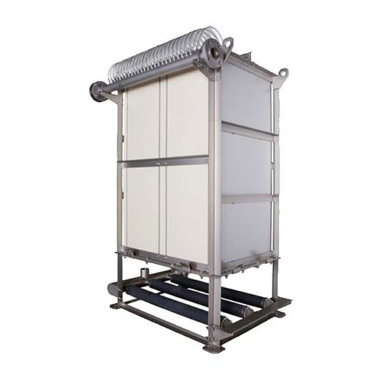
Escherichia coli and Cryptosporidium efficiently. Outline of “TMR090 Series” “TMR090 Series” is the membrane module composed of the element block and the aeration block. The element block contains a number of membrane elements set at equal clearance, each of which has flat sheet membranes fixed on both sides of ABS panel. Each element is connected via polyurethane tube to the permeated water manifold. - Page 6 (1) Shape of Element The membrane element is a flat sheet type as shown in Fig.I-4. At the normal filtration operation, the sludge accumulated on the membrane surface is cleaned up effectively with upward water stream generated with the scouring air supplied from the air diffusers installed at the bottom side (Fig.I-5).
- Page 7 Fig.I-7) compared to other membranes. The average pore size is 0.08 micron meter. 3.0 micron 3.0 micron Toray PVDF Other Membrane Membrane Fig. I-6 Membrane Surface (photo) PVDF Toray PVDF Membrane Other Membrane 東レ BF014 東レ BF014 クボタ クボタ Pore Size (micron) Fig. I-7 Pore Size Distribution GIRE-097-2-2...
- Page 8 (5) Fine-bubble Air Diffusers "TMR090 Series" is equipped with fine-bubble air diffusers, which significantly reduces the daily cleaning operation of air diffusers and additionally increase the oxygen dissolution efficiency to 1.3-2.0 times as high as the coarse-bubble diffusers.
-
Page 9: For Safe Operation Of "Tmr090 Series
FOR SAFE OPERATION OF “TMR090 Series” Before using “TMR090 Series”, please thoroughly read this Instruction Manual and follow the instructions described in this manual, especially the safety precautions shown below. The details of each precaution are described in the relevant chapter. -
Page 10: Operation And Maintenance
Operation and Maintenance WARNING Don't use the treated water for drinking. Before discharging the treated water to the environment or reusing WARNING it, make sure to analyze its quality and confirm that the water quality meets the intended purpose. Don't burn the membranes without appropriate facilities since WARNING harmful Hydrogen fluoride (HF) gas is generated at burning. -
Page 11: Chemical Cleaning Of Element
CAUTION deterioration is detected at the inspection. CAUTION Prevent “TMR090 Series” from freezing at any time. Please take care not to dry the membranes when taking "TMR090 CAUTION Series" out of the liquid for the inspection or the maintenance. If the wet membrane is dried up again, the permeability of the membrane might be decreased seriously. - Page 12 If any abnormality is found in the equipment during chemical WARNING cleaning, immediately stop operation and check it. If chemical is injected forcibly directly with the chemical feed pump or by any other means, the internal pressure of the elements will WARNING increase and the elements will get damaged.
-
Page 13: Specifications And Performance Of "Tmr090 Series
III. SPECIFICATIONS AND PERFORMANCE OF “TMR090 Series” Specifications of Element TableIII-1 and Fig.III-1 shows the specifications and the appearance of the element for TMR090 Series, respectively. Table III-1 Specifications of Element (TSP-50100) Model name TSP-50100 Membrane configuration Flat sheet Application... -
Page 14: Specifications And Performance Of "Tmr090 Series" Module
Specifications and Performance of "TMR090 Series" Module Table III-3 shows the specifications of "TMR090 Series" modules. EPDM is equipped as standard membrane material for the diffuser. EPDM has been used in a lot of application for sewage treatment and industrial wastewater treatment and wears well. - Page 15 Not higher than 1.0 quality This value is a guarantee value of Toray that can be attained when the modules are installed and operated appropriate under the standard conditions as specified in this Instruction Manual and Operation and Maintenance Guideline during a period specified separately by Toray.
-
Page 16: Membrane Filtration Process Design For "Tmr090 Series
The standard filtration pattern time chart, the schematic flow diagram of the membrane filtration, the layout of “TMR090 Series” modules in the membrane submerged tank, and the piping procedures are described in this section. These would help you design the membrane filtration process with “TMR090 Series”. -
Page 17: Flow Diagram Of Membrane Filtration Process
Flow Diagram of Membrane Filtration Process Two schematic flow diagrams of the membrane filtration process are shown below. One is for the gravity filtration with water head difference and the other is with suction pump. Major necessary peripheral devices for membrane filtration process are described in the latter part of this section. - Page 18 In order to obtain enough suction pressure for the filtration considering the friction loss of pipe and valves, the permeate water outlet should be located sufficiently below the liquid level of the membrane submerged tank (normally 3 m below water level or lower). It is recommended that the piping from the permeate water manifold to the permeate water outlet should directly penetrate the tank wall, as shown in Fig.IV-2.
- Page 19 A range of methods can be applied for this air removal such as vacuum pump, ejector or manual water injection. Please contact TORAY or refer to the engineering manual for the details. (3) Necessary devices for membrane filtration process Major necessary peripheral devices to operate membrane filtration process are explained below.
- Page 20 In the case of operating a number of “TMR090 Series” modules simultaneously in one train, it is advised to install one flow rate controller for one train of the modules.
- Page 21 Relaxation Air supply unit (such as a blower) This unit supplies air to the air diffusers of "TMR090 Series" module. The air flow rate supplied to the module should be always within the range of "Scouring Air Flow Rate" indicated in Table III-3.
-
Page 22: Layout Of "Tmr090 Series" Modules In Membrane Submerged Tank
3. Layout of “TMR090 Series” Modules in Membrane Submerged Tank (1) Layout of Modules in Membrane Submerged Tank Fig.IV-5a shows how the liquid circulates in the membrane submerged tank. An upward flow is generated by supplying the air from the fine bubble air diffuser located at the lower side of the membrane modules. - Page 23 W1 : 380 to 680 mm (ii) W2 : 430 to 730 mm (iii) W3 : W3 should be as short as possible (normally about 400 mm) within the range allowing piping and maintenance work. (iv) L1 : L1, the distance between the top of the element and the liquid level of the tank, should be 300 mm or over at any time of the operation.
- Page 24 Tank wall Module Module Module “ ” “ ” “ ” 2 × W3 Oxygen Supplying Aeration Equipment Fig.IV-7 Membrane Module Layout in Membrane Submerged Tank with other aeration equipment (top view) Please keep twice of W1 of the distance between the modules and other aeration equipment in the case shown in Fig.IV-8, Tank wall 2 ×...
-
Page 25: Piping
Piping The procedures of the pipe arrangement for the air diffusers and the permeate water manifold are described in this section. The connections of the air diffuser and the permeate water manifold are shown in the module drawings attached to this manual. (1) Pipe Arrangement for the air diffusers The pipe from the air supply device (the blower) is connected to the air diffusers with the screws (A) as shown in Fig.IV-9-11. - Page 26 Air Flow Meter Header Pipe Header Pipe Air Diffuser Fig.IV-10 Example of Piping to Air diffusers for TMR090-100S (Installation of One Unit) Air Flow Meter Header Pipe Header Pipe Air Diffuser Fig.IV-11 Example of Piping to Air Diffusers for TMR090-100S (Installation of Multiple Units) GIRE-097-2-2...
- Page 27 Blower(s) and air piping for membrane scouring should be completely separated from the biological aeration system so that the membrane scouring air flow rate would not be affected by DO control in oxidation process. Membrane scouring blower(s) must have enough capacity to satisfy the scouring air flow rate requirements for all modules.
- Page 28 (2) Piping to Manifold Fig.IV-12 and Fig.IV-13 give two examples of leading permeated water from the Membrane Submerged Tank. Fig.IV-12 shows downward piping and Fig.IV-13 shows upward piping. The downward piping is for the gravity filtration. The upward piping is for the operation with suction pump located above the Membrane Submerged Tank.
-
Page 29: Installation Of "Tmr090 Series
Please use forklift for moving the box on site. Do not stand or sit on the top of the box. When lifting "TMR090 Series", please set a hook on all hang holes and lift it keeping it horizontal with chains or slings. Please use special hanger (drawing attached) in case of limited hanging space. -
Page 30: Checking Products
The protective covers are fit in the right position. Storage Products Please store "TMR090 Series" indoors under lower than 40 degree C of the temperature, keep it horizontal and avoid direct sunlight to prevent the membrane from deterioration. Throughout the entire process of installation work from transportation to operation startup, please take adequate measures to protect the elements and other components from damage. -
Page 31: Installation Products
Be careful not to damage the rubber parts of air diffusers and CAUTION element fixing brackets. 5. Installation Products Please check the followings before module installation: (1) All the necessary works in the membrane submerged tank has been completed. (2) Tank and pipes have been cleaned. (3) Please confirm that there is no leakage of water or air from the tanks or pipes. - Page 32 Please flush out the permeate water line before connection. Don't apply pressure to the permeate side of the element, or the element may get damaged. When lifting “TMR090 Series”, please attach chains or slings to it DANGER and lift it straight upward calmly to prevent “TMR090 Series” from shaking.
-
Page 33: Start Of Operation
START OF OPERATION Clean Water Operation (1) Checks and Arrangements At first, please make the following inspections and arrangements in this order: Check that the air diffusion pipe and the permeated water pipes are connected properly. Check that the membrane submerged tank has been cleaned up completely and then remove the protective cover from top of the module. -
Page 34: Seeding Sludge Injection
Check the control devices work well during the clean water operation. Start filtration with clean water. Measure and record the trans-membrane pressure and water temperature at designed filtration rates (at a normal, maximum and minimum flow rate). Maintain such records. Stop the filtration and the air supply as soon as the above tests finish. - Page 35 sludge MLSS does not reach 7,000 mg/L, and gradually increase the flux considering F/M ratio. Initial seeding sludge is not yet acclimataized to the MBR operation and in such condition filtration with higher flux may lead to membrane fouling. Sludge parameters such as MLSS and sludge filterability should be checked frequently to assess the actual sludge condition.
-
Page 36: Operation Control
OPERATION CONTROL Standard Operating Conditions Table VII-1 shows standard operating conditions for “TMR090 Series”. These operating parameters such as MLSS, sludge viscosity, DO (dissolved oxygen concentration) and pH should be kept in the range of the standard operation conditions given in Table VII-1 in order to ensure stable operation. - Page 37 Avoid abrupt changes in pH, temperature, trans-membrane CAUTION pressure or any other conditions even if they are within the standard operating conditions (Table VII-1). CAUTION Replace consumable parts regularly after inspection. CAUTION Protect the modules from freezing. GIRE-097-2-2...
-
Page 38: Operating Parameters
Operating Parameters The performance of “TMR090 Series” varies in accordance with the raw water quality and the operating conditions. It is recommended to monitor and record the values of operating parameters in order to achieve the stable operation and the expected performance with “TMR090 Series”. -
Page 39: Basic Control Philosophy
Basic Control Philosophy Listed below is the basic control philosophy for operating “TMR090 Series”. Please note that this is a basic one and detailed control philosophy for each project shall be examined carefully on a case-by-case basis. (1) Suction pump: Run intermittently by timer (9 min on/1 min off), VFD control for flow rate, stop filtration by low MBR tank level or high TMP. -
Page 40: Daily Inspection
Daily Inspection For the operating parameters listed in the preceding section, perform inspection periodically, at least once per week, as follows. Please check trends of these data and take necessary actions before too late. (1) Trans-membrane pressure Please check that the trans-membrane pressure is stable. Please carry out chemical cleaning before the trans-membrane pressure increase by 5 kPa (50 mbar) from its initial operating level at the same permeated water flow rate. - Page 41 sludge characteristics, check the operating condition, such as BOD load, MLSS concentration, DO, pH, temperature and/or wastewater component, and take appropriate actions. (4) MLSS MLSS concentration in the membrane submerged tank should be normally 7,000 to 18,000 mg/L. If MLSS is too low, please decrease excess sludge discharge rate. If MLSS is too high, please check the return activated sludge flow rate and if it is low, please increase the RAS rate at proper value.
- Page 42 (12) Pretreatment system In addition to operating parameters for the operation of “TMR090 Series”, please check the state of the pretreatment system (particularly the fine screen system) regularly and remove the accumulated trashes whenever necessary.
-
Page 43: Maintenance Of "Tmr090 Series
VIII. MAINTENANCE OF “TMR090 SERIES” Maintenance Items and Maintenance Frequency To maintain the performance of “TMR090 Series”, perform the following at specified intervals: Clean the air diffusers (when extraordinary uneven diffusion is found). Chemical cleaning of the element (when the trans-membrane pressure has risen by 5 kPa (50 mbar) or more from its initial operating level at the same permeated water flow rate or every 6 months, whichever comes first). -
Page 44: Air Diffuser Cleaning
Air Diffuser Cleaning "TMR090 Series" is equipped with fine-bubble air diffusers, which significantly reduces the daily cleaning operation of air diffusers compared to the coarse-bubble diffusers. Usually in domestic wastewater treating cases, no operation change is required. However, in the unlikely event of diffuser clogging, uneven air diffusion may cause membrane clogging and elements damage in the worst case. -
Page 45: Chemical Cleaning Of Element
3. Chemical Cleaning of Element Chemical cleaning of element should be conducted before the trans-membrane pressure rises to excess. Such a pressure increase can be caused when contaminants clog the pores of the membrane surface. The timing of chemical cleaning is determined as follows: When the trans-membrane pressure rises by 5 kPa (50 mbar) from its initial operating level at the same permeated water flow rate or every 6 months, whichever comes first. -
Page 46: Handling Of Chemical Agents
* Oxalic acid should not be applied when wastewater contains calcium, since calcium oxalate may form on the membrane surface which can choke membrane pores. 5. Handling of Chemical Agents The chemical agents used for chemical cleaning are harmful to the health when in contact with the skin. - Page 47 dragging it. (c) Take care not to cause leak, spillover or spattering. Don't cause dust or vapor. (d) Firmly seal the container after use. (e) Thoroughly wash your hands and face and rinse out your mouth after using chemicals. Don't eat or drink anything in the working place except in a designated place. (g) Don't bring gloves or other contaminated protectors into the rest area.
- Page 48 prevent direct contact with air. (b) Use corrosion-resistant containers for storage. The chemical agents used for chemical cleaning are harmful to the health. When handling chemicals, wear protective goggles, WARNING protective gloves and other protectors. Make sure to check the details of its material safety data sheet (MSDS) beforehand.
-
Page 49: Chemical Cleaning Procedure
Chemical Cleaning Procedure (1) Element Chemical Cleaning Procedure Firstly please slowly inject the chemical via the permeated water nozzle into the elements until it percolates through the membranes. Do not apply too high pressure (>10 kPa or 100 mbar) when injecting the chemical. Some injecting methods are shown below. Chemical Cleaning with the chemical tank located at the bottom (Fig.VIII-1) Confirm that the chemical injection valve is closed and that the chemical feed pump is stopped. - Page 50 Chemical cleaning with the chemical tank located above the membrane submerged tank (Fig.VIII-2) Confirm that the chemical injection valve is closed. (ii) Provide the chemical tank with specified amounts of the chemical. (iii) Stop filtration, stop aeration, and close the filtrate valve. (iv) Slowly open the chemical injection valve to inject chemicals.
- Page 51 (iii) Stop filtration, stop aeration and close the permeated water valve. (iv) Surely open the relief valve. Start the chemical feed pump. (vi) Confirm the smooth return of the chemical to Chemical tank when it spouts from the outlet of relief piping. If the spouting is too much, adjust the feeding rate of chemical.
- Page 52 (2) Precautions for Element Chemical Cleaning Keep the injecting pressure below 10 kPa (100 mbar). Avoid forcibly applying pressure directly with the pump or by any other means. A higher pressure will damage membrane elements and modules. Please note that injecting pressure may rise up after injecting half of the chemical.
-
Page 53: Lifting Procedure
Lifting Procedure Please take the following steps to lift “TMR090 Series” modules for maintenance, in the case that the modules are installed on the bottom of the tank with using anchors. Discharge completely activated sludge liquid from the tank. -
Page 54: Replacement Of Element Fixing Gaskets
Replacement of Element Fixing Gaskets Please at first lift "TMR090 Series" modules out of the tank according to the lifting procedure described above and take the following steps to replace the element fixing comb gaskets (EPDM rubber). The bolt size is M10. -
Page 55: Element Replacement
9. Element Replacement Please at first lift "TMR090 Series" module out of the tank according to the lifting procedure described in the former section and replace elements. Pull the permeate tubes, which are to be replaced, out from element nozzles and manifold nozzles. - Page 56 Be careful not to damage the comb gaskets (EPDM rubber) of the CAUTION element fixing bracket. Be careful not to damage the element during the element CAUTION replacement works. Particularly, be careful not to scratch the membrane surface. Optional extras: The tool to pull up an element GIRE-097-2-2...
-
Page 57: Air Diffuser Replacement
10. Air Diffuser Replacement At first, please lift the module out of the tank according to the lifting procedure described in the former section. Then, take the following steps to replace the air diffuser. Bolt size is M10. TMR090-050S has one header pipe and TMR090-100S has two header pipes. TMR090-100S has six air diffuser pipes with two different lengths. - Page 58 the pipe support and the length of the diffuser pipes. No Slit Area shall be located at top and bottom when connecting to the header pipe. Element block (5) Fit the header pipes to the aeration block while fixing air diffusers on the pipe supports.
-
Page 59: Storage Products After Use
11. Storage Products after Use Please take the following steps to preserve the used “TMR090 Series” modules for a long time until future re-operation. (1) Drain the sludge in the membrane submerged tank. (2) Clean the modules with clear water and wash out the remaining sludge on the module surface as well as tank wall using hose. -
Page 60: Disposing Procedure
12. Disposing Procedure When disposing of the membrane after use, please follow below general procedure. (1) Clean up the membrane module with water. After that it is better to dry up the module for your easy handling. (2) Dispose of the module or each constituent following local regulation for waste disposal (landfill, incineration...). -
Page 61: Replacement Parts List
REPLACEMENT PARTS LIST Please contact us for the details of the specifications, Name Frequency Type No. Permeate Tube Every 3 years or when EBL-TUBE-050 deterioration detected, EBL-TUBE-100 (50 sets/100 sets) whichever comes first Element TMR090- Middle Every 3 years or when GASKET090-050M fixing 050S... -
Page 62: Troubleshooting
TROUBLESHOOTING Most of troubles in the operation of “TMR090 Series” are related to abnormal membrane scouring aeration, too late chemical cleaning, lack of maintenance of the pretreatment system. The following table shows such troubles and countermeasures against them: Table IX-1 Troubleshooting... -
Page 63: Appendix
APPENDIX Following information is provided in the separate-attached document: (1) Assembly of Modules. (2) Assembly of Brackets. (3) Assembly of Guide Rail System. (4) Assembly of Hangers. (5) Assembly of Element-pick-up tool. (6) Procedure of Paper filter test. This Instruction Manual does not intend to guarantee the results of application of the information provided herein or the safety and the compatibility of this product. - Page 73 6. Additionally it is advisable to check the turbidity and/or TOC (Total Organic Carbon) of the filtrated water which can be an indicator of membrane foulant such as so-called EPC. Measure it routinely and check its trend. Standards of filter paper Used by TORAY JIS P 3801 ASTM E832-81 No.5C...
Need help?
Do you have a question about the TMR090 Series and is the answer not in the manual?
Questions and answers