Table of Contents
Advertisement
Issued in February 2019
TORAY Pressurized PVDF Hollow Fiber
TM
Membrane Module "TORAYFIL
"
Instruction Manual
Model: "HFUG-2020AN"
(type AN)
Toray Industries, Inc.
issued by
Water Treatment & Environment Division
2-1-1, Nihonbashi-Muromachi, Chuo-ku, Tokyo 103-8666 Japan
Tel: +81-3-3245-4557
Fax: +81-3-3245-4913
URL: www.toraywater.com
BJAIJBAC
Advertisement
Table of Contents

Subscribe to Our Youtube Channel
Related Manuals for Toray TORAYFIL HFUG-2020AN


Summary of Contents for Toray TORAYFIL HFUG-2020AN
- Page 1 Issued in February 2019 TORAY Pressurized PVDF Hollow Fiber Membrane Module "TORAYFIL " Instruction Manual Model: "HFUG-2020AN" (type AN) Toray Industries, Inc. issued by Water Treatment & Environment Division 2-1-1, Nihonbashi-Muromachi, Chuo-ku, Tokyo 103-8666 Japan Tel: +81-3-3245-4557 Fax: +81-3-3245-4913 URL: www.toraywater.com...
-
Page 2: Table Of Contents
Content Introduction ....................1 1. Characteristics of Toray "HFUG series" Membrane Modules ....1 2. About “type AN” ..................2 3. Applications of Toray "HFUG-2020AN" Membrane Module ...... 2 II. For Your Safety .................... 3 1. Safety Instruction for Unpacking and Installation ........4 2. -
Page 3: Introduction
I. Introduction Toray PVDF Hollow Fiber Membrane Module "HFUG series" is a pressurized hollow fiber UF (Ultra Filtration) membrane module developed with polymer science and membrane fabrication technologies accumulated over decades of successful membrane manufacturing at Toray Industries, Inc. The HFUG... -
Page 4: About "Type An
(3) High Mechanical Strength The membrane of HFUG series has very high mechanical strength because it is made of PVDF with the special spinning method developed by Toray. HFUG series provides high integrity and durability under recommended operating conditions. (4) High Chemical Durability... -
Page 5: For Your Safety
For Your Safety Please be sure to read and follow the instructions below before using HFUG-2020AN. This manual should be retained for future reference. Follow the safety precautions as they are intended to protect operators and equipment from various risks such as physical harm and/or property damage. -
Page 6: Safety Instruction For Unpacking And Installation
1. Safety Instruction for Unpacking and Installation Be sure to wear safety gear such as rubber gloves and safety glasses for unpacking. The membrane is packaged in sodium hypochlorite solution (100 mg/L). If the solution happens to splash onto the skin, Instruction wash the affected part with running water. - Page 7 Housing type joints are applied for connecting the modules of HFUG-2020AN to the piping. Follow the instruction of the Housing Type Joints Set-up Guide at the connection point. Wrong Instruction connections may damage the modules. Keep the connection surface free of any dirt or oils. Prohibited Be sure to install the modules vertically for effective air scrubbing.
-
Page 8: Safety Instruction For Filtration Operation
2. Safety Instruction for Filtration Operation Flush all the piping out with clean water and make sure no debris is remaining in the piping prior to connecting the modules. Instruction Confirm that the preservative chemical in the modules is completely drained out before starting the filtration operation. - Page 9 Do not exceed the maximum applicable pressure of 300 kPa (43.5 PSI). Higher pressures can damage the modules. Do not exceed the maximum temperature of 40 degree C (104 degree F). Prohibited higher temperature damages the modules. Do not freeze the membrane modules. Prohibited The operating conditions, including the filtration flux and the periodical physical...
-
Page 10: Safety Instruction For Chemical Cleaning
3. Safety Instruction for Chemical Cleaning Take special precautions when handling chemicals during chemical cleaning. Wear the safety gear such as safety glasses and protective gloves. If chemicals come in direct contact with your skin or your Instruction clothes, treat the contacted part appropriately based on the SDS. Do not mix sodium hypochlorite with acid. -
Page 11: Safety Instruction For Disposal
4. Safety Instruction for Disposal When dispose the modules, please apply a service of a qualified waste disposing company. When the module is to be incinerated, please apply the appropriate facilities in which hydrogen fluoride (HF) gas can Instruction be neutralized. HF gas is generated with the incineration of membrane. -
Page 12: Specifications Of Toray "Hfug-2020An" Membrane Module
III. Specifications of Toray "HFUG-2020AN" Membrane Module Table 1. Specifications of membrane * Membrane Material PVDF (Polyvinylidene fluoride) Nominal Pore Size 0.01 micron Maximum * 300 kPa (43.5 PSI) Trans-Membrane Pressure Normal Operation Lower than 200 kPa (29.0 PSI) Storage and Operating 0 –... - Page 13 Table 3. Cleaning limits * Cleaning pH Range 0 – 12 0 – 40 degree C Cleaning Temperature Range (32 – 104 degree F) Maximum Concentration of NaClO as Cl 3,000 mg/L (10 < pH < 12) Maximum NaClO Exposure 1,000,000 mg/L hours (lifetime contact time) as Cl Maximum Acid Contact Time...
- Page 14 Handle and operate the modules within the ranges and the limits indicated in Table 1 to 4. Operation out of these ranges or limits may damage the modules, and affect filtration performance.
-
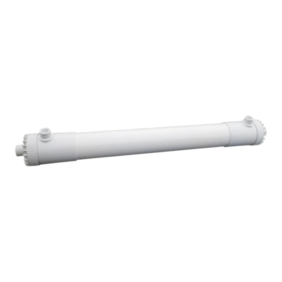
Page 15: Configuration Of Toray "Hfug-2020An" Membrane Module
IV. Configuration of Toray "HFUG-2020AN" Membrane Module (1): Filtrate Outlet / Inlet of Backwash Water (2): Air Outlet / Backwash Water Outlet (3): Feed Water Inlet / Air Inlet / Drain Outlet Connections Pipe fitting outer diameter Connectors mm (in) Housing type 89.1 (3 1/2”) -
Page 16: Installation
Installation The standard method to install the membrane modules is described below. 1. Unpack the membrane module from wooden box or corrugated box. 2. Remove plugging plate from each nozzle of the module. 3. Drain out the preservative solution from the module. ... - Page 17 Be careful not to install the module upside down. Confirm the module is installed in the right direction. Do not overtighten the module with the hanging hook and/or the supporting belt, or you may damage the module. Do not allow the hollow fiber membranes to dry even for a few hours, especially in summer.
- Page 18 5. Connect the piping to each connection point of the module with Housing type joints (HFUG-2020AN) (see Fig. 3). The maximum fastening power of the Housing type joints should not exceed 40 Nm. When you tighten or loosen the Housing type joints, make certain to maintain sufficient space prior to the work and be careful not to be wounded by swinging out or clipping your fingers.
-
Page 19: Operation
VI. Operation 1. Filtration (1) Check that all piping is connected appropriately and flushed out prior to the operation. Fig. 3 shows a typical example of piping. Fig. 3 Typical example of piping (2) Make sure the feed water valve (V-1), the drainage valve (V-3) and the valve for the scrubbing air (V-2) are “closed”. - Page 20 Do not open the feed water valve (V-1) quickly, or water-hammer may occur and the module could be damaged. (5) Confirm that the air is out of the module, and then close the air exhaust valve (V-4). (6) Set appropriate volume of filtrate water flow. ...
-
Page 21: Backwash And Air-Scrubbing
2. Backwash and Air-scrubbing The physical cleaning with backwash followed by air-scrubbing should be carried out periodically and automatically for the continuous filtration. The frequency of the physical cleaning mainly depends on the raw water quality (Typical frequency is once every 30 minutes normally for surface water filtration. Please contact us if you need technical support.). - Page 22 feed back the filtrate water from the backwashing tank to the membrane module. During backwash, chemical feed pump can be operated to dose chemical to the backwash water. The dosing chemical is usually sodium hypochlorite and the dosing ratio should be up to 50 mg/L as Cl The flow rate of backwash water is set up in advance for 1.0 to 1.5 times filtrate water flow rate (Do not exceed Max.
- Page 23 If abnormal water quality is detected, check the integrity of the element with PDT (Pressure Decay Test) or DAF (Diffusive Air Flow) Test. The test procedure is provided as the technical information by Toray.
-
Page 24: Toray Maintenance Cleaning
This process is called Toray Maintenance Cleaning (TMC). The TMC is usually held following the backwash and air-scrubbing which does not contain the chemical dosing. The frequency and soaking time of the TMC mainly depends on the raw water quality (Normally once a day and each soaking time are 20 minutes. - Page 25 (1) Open the air exhaust valve (V-4) and the drainage valve (V-3). (2) Open the backwashing valve (V-6), run the NaClO feed pump and the backwashing pump to feed the chemical enhanced backwash water to the membrane module. The flow rate of backwash water is set up in advance for 1.0 to 1.5 times filtrate water flow rate (Do not exceed Max.
- Page 26 If abnormal water quality is detected, check the integrity of the element with PDT (Pressure Decay Test) or DAF (Diffusive Air Flow) Test. The test procedure is provided as the technical information by Toray.
-
Page 27: Basic Trans-Membrane Pressure Calculation
4. Basic Trans-Membrane Pressure Calculation To calculate accurate Trans-Membrane Pressure (TMP), it is necessary to involve the height difference of inlet and outlet pressure gauges. Example calculation of TMP TMP = (P ) - (P = (70 - 10) - (20 + 25) = 60 - 45 = 15 kPa Note, the following formula may also be used:... -
Page 28: Temperature Correction Factor
5. Temperature Correction Factor The permeability of the membrane is influenced by temperature mainly because the water viscosity changes with temperature. When you evaluate the permeability correctly, you need to eliminate the temperature effect with the temperature correction factor (TCF) shown in Fig. 6. A Trans-Membrane Pressure (TMP) measured at some real temperature can be converted to 25 degree C corrected TMP with multiplying by TCF at real temperature shown in Fig. -
Page 29: Chemical Cleaning
VII. Chemical Cleaning The chemical cleaning should be carried out to remove foulants accumulated in the membrane pores or sticking to the membrane surface. Carry out the chemical cleaning before the trans-membrane pressure rises up to 200 kPa (29.0 PSI), or the module filtration performance could be reduced significantly. - Page 30 Fig. 7 Flow diagram for chemical cleaning (1) The flow diagram for cleaning simultaneously both outer surface and inside of hollow fiber membranes is shown in Fig. 7. The flow diagram can be changed case by case. Please contact us if you need the information in detail.
- Page 31 (6) Drain the chemical and rinse the cleaning line and the module thoroughly with product water. Take appropriate measures prevent mis-operation or accidents that could cause the chemicals to get into the product water. Check the piping and correctly position of each valve before starting the chemical cleaning.
- Page 32 In the case of cleaning with acid and with sodium hypochlorite alternately, rinse the cleaning line and the module with clean water thoroughly after each cleaning. Use product water for rinsing and make sure that pH of the water in the module is in the range between pH 6.5 and 7.5 after rinsing.
-
Page 33: Storage Of Membrane Module
VIII. Storage of Membrane Module Follow the instruction below when you store the modules. Be careful not to freeze the modules. 1. Storage of New Membrane Modules Keep the modules in the original packing in a dark and cool place (0 to 40 degree C). -
Page 34: Replace Preservative Chemical
(2) Long term storage First carry out a chemical cleaning with sodium hypochlorite. Fill the module with the chemical described in Table 7. Use filtrate quality water. Follow the instructions shown in Table 7. Keep the modules sealed with the aqueous chemical solution shown in Table 6 or Table 7. - Page 35 This Instruction Manual does not intend to guarantee the results of application of the information provided herein or the safety and the compatibility of this product. Before using this product, the user is asked to check for its safety and compatibility with the intended purpose.
Need help?
Do you have a question about the TORAYFIL HFUG-2020AN and is the answer not in the manual?
Questions and answers