Table of Contents
Advertisement
Quick Links
Submerged Membrane Module
for MBR
TORAY "MEMBRAY"
"TMR140 Series"
Instruction Manual
Toray Industries, Inc.
Water Treatment Division
1-1, Nihonbashi-muromachi 2-chome, Chuo-ku, Tokyo 103-8666 Japan
Tel: +81-3-3245-4542
Fax: +81-3-3245-4913
URL: http://www.toraywater.com
Published: April 2013
AIRE-064-1-6
Advertisement
Table of Contents

Related Manuals for Toray MEMBRAY TMR140 Series


Summary of Contents for Toray MEMBRAY TMR140 Series
- Page 1 Submerged Membrane Module for MBR TORAY “MEMBRAY” “TMR140 Series” Instruction Manual Toray Industries, Inc. Water Treatment Division 1-1, Nihonbashi-muromachi 2-chome, Chuo-ku, Tokyo 103-8666 Japan Tel: +81-3-3245-4542 Fax: +81-3-3245-4913 URL: http://www.toraywater.com Published: April 2013 AIRE-064-1-6...
-
Page 2: Table Of Contents
Content INTRODUCTION ........................1 Features of MBR ........................1 Outline of “TMR140 Series” ....................2 FOR SAFE OPERATION OF “TMR140 SERIES” ..............5 Unpacking and Installation ....................5 Operation and Maintenance ....................6 Chemical Cleaning of Element ....................7 III. SPECIFICATIONS AND PERFORMANCE OF “TMR140 SERIES”... - Page 3 Storage Products after Use ....................53 Disposing Procedure ......................54 REPLACEMENT PARTS LIST ..................... 55 TROUBLESHOOTING ......................56 APPENDIX ..........................57 Symbols used in this manual This symbol is used to indicate an imminent hazardous situation DANGER which, if not avoided, will result in serious injury or death. This symbol is used to indicate a potentially hazardous situation WARNING which, if not avoided, can result in serious injury or death.
-
Page 4: Introduction
INTRODUCTION Toray "MEMBRAY" is the submerged membrane module suitable for the membrane bioreactor (MBR) that has been developed based on the polymer science and the membrane fabrication technologies accumulated for a long time in Toray Industries, Inc. "TMR140 Series" is a standard model of "MEMBRAY". This manual explains MBR's features and describes the specifications of "TMR140 Series"... -
Page 5: Outline Of "Tmr140 Series
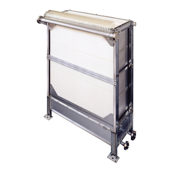
Outline of “TMR140 Series” “TMR140 Series” is the membrane module composed of the element block and the aeration block. The element block contains a number of membrane elements stacked at equal clearance, each of which has flat sheet membranes attached on both sides of ABS panel. Each element is connected via polyurethane tube to the permeated water manifold. - Page 6 (1) Shape of Element The membrane element is a flat sheet type as shown in Fig.I-4. At the normal filtration operation, the sludge accumulated on the membrane surface is cleaned up effectively with upward water stream generated with the scouring air supplied from the air diffusers installed at the bottom side (Fig.I-5).
- Page 7 (see Fig.I-6 and Fig.I-7) compared to other membranes. The average pore size is 0.08 micron meter. 3.0 micron 3.0 micron Toray PVDF Membrane Other Membrane Fig. I-6 Membrane Surface (photo) PVDF...
-
Page 8: For Safe Operation Of "Tmr140 Series
FOR SAFE OPERATION OF “TMR140 SERIES” Before using “TMR140 Series”, please thoroughly read this Instruction Manual and follow the instructions described in this manual, especially the safety precautions shown below. The details of each precaution are described in the relevant chapter Unpacking and Installation When lifting “TMR140 Series”... -
Page 9: Operation And Maintenance
Please install the screen with openings of 3.0 mm or under before the membrane submerged tank. It is recommended to use the CAUTION mesh type screen. Overflow or waste carryover must be avoided at any time. Operation and Maintenance WARNING Don't use permeated water for drinking. -
Page 10: Chemical Cleaning Of Element
Please replace the renewal parts periodically or when the CAUTION deterioration is detected at the inspection. Prevent “TMR140 Series” from freezing at any time. CAUTION Please take care not to dry the membranes when taking "TMR140 Series" out of the liquid for the inspection or the maintenance. If CAUTION the wet membrane is dried up again, the permeability of the membrane might be decreased seriously. - Page 11 When injecting the chemical agents at the chemical cleaning, please confirm beforehand that the modules are completely WARNING submerged in the liquid and the liquid level of the membrane submerged tank is higher by more than 500 mm than the top of the module.
-
Page 12: Specifications And Performance Of "Tmr140 Series
III. SPECIFICATIONS AND PERFORMANCE OF “TMR140 SERIES” Specifications of Element TableIII-1 and Fig.III-1 shows the specifications and the appearance of the element for TMR140 Series, respectively. Table III-1 Specifications of Element (TSP-50150) Model name TSP-50150 Membrane configuration Flat sheet Application Filtration of activated sludge Filtration method Suction filtration... -
Page 13: Specifications And Performance Of "Tmr140 Series" Module
*5 The air supply equipment such as blower shall be designed based on the standard operating conditions shown in Table VII-1. “NL” means air volume as being 0 degree C and 101.325 kPa (1 atm). *7 Please contact Toray if you would like to use Polypropylene diffuser/permeated water manifold. Additional information will be provided. AIRE-064-1-6... - Page 14 30 - 140 60 - 280 This value is just a reference value and not a guarantee value of Toray. Sustainable operating filtration flow capacity varies among the plant depending on the type of wastewater, total process design and operating condition. In case of industrial wastewater application, it is strongly recommended to conduct a pilot test before membrane tank designing.
-
Page 15: Membrane Filtration Process Design For "Tmr140 Series
MEMBRANE FILTRATION PROCESS DESIGN FOR “TMR140 SERIES” The standard filtration pattern time chart, the schematic flow diagram of the membrane filtration, the layout of “TMR140 Series” modules in the membrane submerged tank, and the piping procedures are described in this section. These would help you design the membrane filtration process with “TMR140 Series”. -
Page 16: Flow Diagram Of Membrane Filtration
Flow Diagram of Membrane Filtration Two schematic flow diagrams of the membrane filtration process are shown below. One is for the gravity filtration with water head difference and the other is with suction pump. Major necessary peripheral devices for membrane filtration process are described in the latter part of this section. - Page 17 level of the membrane submerged tank (normally 3 m below water level or lower). It is recommended that the piping from the permeate water manifold to the permeate water outlet should directly penetrate the tank wall, as shown in Fig.IV-2. Also if the permeate water outlet is located in the open air, it is recommended to make the outlet pipe U-shape to seal the piping with water.
- Page 18 A range of methods can be applied for this air removal such as vacuum pump, ejector or manual water injection. Please contact TORAY or refer to the engineering manual for the details. (3) Necessary devices for membrane filtration process Major necessary peripheral devices to operate membrane filtration process are explained below.
- Page 19 Fine screen The wastewater should be treated by screen with openings of 3.0 mm or under before flowing into the membrane submerged tank, otherwise the modules are polluted and clogged with foreign substances seriously. It is recommended to use the mesh type screen. Overflow or waste carryover must be avoided at any time. Flow control device A flow rate controller, a flow meter combined with an automatic control valve, or a flow meter combined with VFD controlled suction pump should be installed on the...
- Page 20 a = 1,000 mm (= 10 kPa, 100 mbar), b = 3,000 mm (= 30 kPa, 300 mbar) PIA readings; Filtration (pump ON) Relaxation (pump OFF) P1 (kPa) P2 (kPa) In this case, differential pressure (dP) is calculated as follows; dP= (P1 - P1 ) - (P2...
-
Page 21: Layout Of "Tmr140 Series" Modules In Membrane Submerged Tank
3. Layout of “TMR140 Series” Modules in Membrane Submerged Tank (1) Layout of Modules in Membrane Submerged Tank Fig.IV-5a shows how the liquid circulates in the membrane submerged tank. An upward flow is generated as the air is supplied from the lower side of the membrane modules. The flow then goes downward along both sides of the element block. - Page 22 W1 : 380 to 680 mm (ii) W2 : 430 to 730 mm (iii) W3 : W3 should be as short as possible (normally about 400 mm) within the range allowing piping and maintenance work. (iv) L1 : L1, the distance between the top of the element and the liquid level of the tank, should be 500 mm or over at any time of the operation.
- Page 23 Tank wall Module Module Module 2 X W3 Oxygen Supplying Aeration Equipment Fig.IV-7 Membrane Module Layout in Membrane Submerged Tank with Other Aeration Equipment (top view) Please keep twice of W1 of the distance between the modules and other aeration equipment in the case shown in Fig.IV-8, Tank wall 2 ×...
-
Page 24: Piping
Piping The procedures of the pipe arrangement for the air diffusers and the permeate water manifold are described in this section. The connections of the air diffuser and the permeate water manifold are shown in the module drawings attached to this manual. (1) Pipe Arrangement for the air diffusers The pipe from the air supply device (the blower) is connected to the air diffusers with the flange (A). - Page 25 (2) Piping to the manifold Fig.IV-10 and Fig.IV-11 give two examples of leading permeated water from the Membrane Submerged Tank. Fig.IV-10 shows downward piping and Fig.IV-11 shows upward piping. The downward piping is for the operation with natural water head. The upward piping is for the operation with suction pump in the case that the pump is located above the Membrane Submerged Tank.
-
Page 26: Installation Of "Tmr140 Series
INSTALLATION OF “TMR140 SERIES” Preparatory Procedure (1) Make sure the transportation plan for “TMR140 Series” including a carry-in route. (2) Arrange all necessary equipments for unloading “TMR140 Series” from the truck, such as forklift. (3) Prior to installation, please confirm that all necessary works in the membrane submerged tank are completed. -
Page 27: Checking Products
Checking Products Please check the followings soon after carrying in “TMR140 Series”: All items are delivered as stated in the shipping ticket. No damage is caused in transit. The protective covers are fit in the right position. Storage Products Please store "TMR140 Series" indoors under lower than 40 degree C of the temperature, keep it horizontal and avoid direct sunlight to prevent the membrane from deterioration. -
Page 28: Installation Products
Please check the tie-in with the assembly drawings attached at the end of this manual. And please contact TORAY beforehand if you want to install the module in the tank without using anchors (e.g., using guide rails instead). - Page 29 Element block Aeration block TMR140-050S TMR140-100S b. TMR140-200W Model "TMR140-200W" consists of two element blocks and one aeration block. Each element block has one manifold and each manifold has one blank flange at the end. Please remove beforehand a blank flange from both element blocks which would be an obstacle when jointing those two element blocks.
- Page 30 I-beam hanger*, and next, please put the other (upper) element blocks on the intermedate blocks using I-beam hanger*. * Reference drawings of connection plates and hanger are supplied by Toray, however these are just for your reference. Design, manufacturing and usage of these parts shall be done with OEM’s responsibility considering local safety regulation.
- Page 31 (4) Plumbing in Permeate Water Manifold Please take the following steps for each module type. The manifold is shipped from the factory with one blank flange furnished at one end. Please connect the manifold to the permeate water line at the other end. It is requested for the buyer to get and use the flange fit for the connection of the manifold if necessary.
- Page 32 Use chains or slings compatible with lifting weight. DANGER Never climb the module. Please set up the foothold when DANGER installation. Use protective equipments to ensure the safety. CAUTION Don't apply pressure to the permeate side. AIRE-064-1-6...
-
Page 33: Start Of Operation
START OF OPERATION Clean Water Operation (1) Checking items before operation At first, please make the following inspections and arrangements in this order: Check that the air diffusion pipe and the permeated water pipes are connected properly. Check that the element block is securely installed on the aeration block. Check that the membrane submerged tank has been cleaned up completely and then remove the protective cover. -
Page 34: Seeding Sludge Injection
Check the control devices work well during the clean water operation, Start filtration with clean water. Measure and record the trans-membrane pressure and water temperature at designed filtration rates (at a normal, maximum and minimum flow rate). Maintain such records. Stop the filtration and the air supply as soon as the above tests finish. - Page 35 considering F/M ratio. Initial seeding sludge is not yet acclimatized to the MBR operation and in such condition filtration with higher flux may lead to membrane fouling. Sludge parameters such as MLSS and sludge filterability should be checked frequently to assess the actual sludge condition. Check the air diffuser cleaning procedure and confirm it works.
-
Page 36: Operation Control
VII. OPERATION CONTROL Standard Operating Conditions Table VII-1 shows standard operating conditions for “TMR140 Series". These operating parameters such as MLSS, sludge viscosity, DO (dissolved oxygen concentration) and pH should be kept in the range of the standard operation conditions given in Table VII-1 in order to ensure stable operation. - Page 37 Analyze the quality of the permeate water to ensure that the water WARNING quality meets the intended purpose before actual use. Don't use chemicals, toxic agents, oils or other substances that CAUTION can adversely affect activated sludge. ABS supporting panel may get chemical cracks by some organic CAUTION solvent, such as alcohols and oils, and some synthetic detergents.
-
Page 38: Operating Parameters
Operating Parameters The performance of “TMR140 Series” varies in accordance with the raw water quality and the operating conditions. It is recommended to monitor and record the values of operating parameters in order to achieve the stable operation and the expected performance with “TMR140 Series”. -
Page 39: Basic Control Philosophy
Basic Control Philosophy Listed below is the basic control philosophy for operating “TMR140 Series”. Please note that this is a basic one and detailed control philosophy for each project shall be examined carefully on a case-by-case basis. (1) Suction pump: Run intermittently by timer (9 min on/1 min off), VFD control for flow rate, stop filtration by low MBR tank level or high TMP. -
Page 40: Daily Inspection
Daily Inspection For the operating parameters listed in the preceding section, perform inspection periodically, at least once per week, as follows. Please check trends of these data and take necessary actions before too late. (1) Diffused air conditions Please check that the fixed amount of air within the standard range is supplied from the diffuser by checking air flow-meter and pressure gage of the air supply line. - Page 41 (4) Water temperature The desirable water temperature is 15 degree C to 40 degree C. If the temperature is out of this range and the activated sludge property is not good, it is recommendable to install temperature control device to cool or heat the liquid. (5) DO Any point in the aeration tank and the membrane submerged tank should be kept at oxic condition.
- Page 42 This is almost same as what is usually measured in the CAS plant, the only difference is that MBR sludge needs to be diluted by permeate water (5-fold) to be measureable with usual method. This SV value can be an on-site indicator of sludge property and we recommend conducting this measurement routinely and checking the trend of the daily value in association with other inspection items.
-
Page 43: Maintenance Of "Tmr140 Series
CAUTION Be sure to use the specified types of the replacement parts. Please contact TORAY for the detailed specifications and the CAUTION procurement routes for replacement parts Insert the tube securely into the foot of the nozzle when replacing CAUTION the tube. -
Page 44: Air Diffuser Cleaning
Air Diffuser Cleaning The clogging of diffuser holes causes uneven air diffusion and membrane clogging, and the elements are broken in the worst case. Please clean the air diffusers at least once a day or more to prevent such trouble (it is recommended to install the automatic air diffuser cleaning system with automatic valves). - Page 45 (2) Air diffuser cleaning procedure - Practical design For multiple module operation, the flushing procedure described in the previous section can be applied for each module. However, a more convenient and simple approach is shown in Fig. VIII-1. Each inlet point of the air diffuser should be connected to each of two air headers, and each header equipped with two valves (automatic valves are strongly recommended) at the inlet point and end point (both higher than water level).
-
Page 46: Chemical Cleaning Of Element
3. Chemical Cleaning of Element Chemical cleaning of element should be conducted when the trans-membrane pressure rises to excess. Such a pressure increase can be caused when contaminants clog the pores of the membrane surface. The timing of chemical cleaning is determined as follows: (1) When the trans-membrane pressure rises by 5 kPa (50 mbar) from its initial operating level at the same permeated water flow rate or every 6 months, whichever comes first. -
Page 47: Handling Of Chemical Agents
Handling of Chemical Agents The chemical agents used for chemical cleaning are harmful to the health when in contact with the skin. When handling chemicals, wear protective goggles, protective gloves and other protectors. Make sure to check the details of its material safety data sheet (MSDS) and the instructions given below beforehand. - Page 48 chemicals. Don't eat or drink anything in the working place except in a designated place. (g) Don't bring gloves or other contaminated protectors into the rest area. (h) Forbid unauthorized entry to the place where chemicals are handled. Wear appropriate protectors to avoid inhalation, eye or skin contact, and direct contact with your clothes.
- Page 49 The chemical agents used for chemical cleaning are harmful to the health. When handling chemicals, wear protective goggles, WARNING protective gloves and other protectors. Make sure to check the details of its material safety data sheet (MSDS) beforehand. If chemicals should stick to your skin or clothes, immediately wash WARNING it away with a large amount of running water.
-
Page 50: Chemical Cleaning Procedure
Chemical Cleaning Procedure (1) Element Chemical Cleaning Procedure Firstly please slowly inject the chemical via the permeated water nozzle into the elements until it percolates through the membranes. Do not apply too high pressure (>10 kPa or 100 mbar) when injecting the chemical. Some injecting methods are shown below. Chemical cleaning with the chemical tank located at the bottom (Fig.VIII-2) Confirm that the chemical injection valve is closed and that the chemical feed pump is stopped. - Page 51 Chemical cleaning with the chemical tank located above the membrane submerged tank (Fig.VIII-3) Confirm that the chemical injection valve is closed. (ii) Provide the chemical tank with specified amounts of the chemical. (iii) Stop filtration, stop aeration, and close the permeated water valve. (iv) Slowly open the chemical injection valve to inject chemicals.
- Page 52 (iii) Stop filtration, stop aeration and close the permeated water valve. (iv) Surely open the relief valve. Start the chemical feed pump. (vi) Confirm the smooth return of the chemical to Chemical tank when it spouts from the outlet of relief piping. If the spouting is too much, adjust the feeding rate of chemical.
- Page 53 (2) Precautions for Element Chemical Cleaning Keep the injecting pressure below 10 kPa (100 mbar). Avoid forcibly applying pressure directly with the pump or by any other means. A higher pressure will damage membrane elements and modules. Please note that injecting pressure may rise up after injecting half of the chemical.
- Page 54 Before starting injecting chemical to elements, confirm that the WARNING liquid surface is more than 500 mm higher than the top of the module. Stop the aeration during chemical cleaning, or the membrane may CAUTION get damaged. AIRE-064-1-6...
-
Page 55: Lifting Procedure
Lifting Procedure Please take the following steps to lift “TMR140 Series” modules for maintenance. (1) If guide rail system is not installed in the membrane tank, drain the activated sludge from membrane tank. (2) Disconnect the manifold from the permeate water line and disjoint the bolts jointing the element block with the aeration block in case bolts/nuts are applied for connecting both blocks. -
Page 56: Storage Products After Use
Storage Products after Use Please take the following steps to preserve the used “TMR140 Series” modules for a long time until future re-operation. (1) Drain the sludge in the membrane submerged tank. (2) Clean the modules with clear water and wash out the remaining sludge on the module surface as well as tank wall using hose. -
Page 57: Disposing Procedure
Disposing Procedure When disposing of the membrane after use, please follow below general procedure. (1) Clean up the membrane module with water. After that it is better to dry up the module for your easy handling. (2) Dispose of the module or each constituent following local regulation for waste disposal (landfill, incineration...). -
Page 58: Replacement Parts List
REPLACEMENT PARTS LIST Please contact TORAY for the details of the specifications.. (1) TMR140-050S Required Quantity per Module Name Frequency Type No. of replacement parts TMR140-050S Every 3 years or when EBL-TUBE-050 (50pcs set) Permeate Tube deterioration detected, EBL-TUBE-100 (100pcs set) -
Page 59: Troubleshooting
TROUBLESHOOTING Most of the troubles in the operation of “TMR140 Series” are related to abnormal membrane scouring aeration, too late chemical cleaning, lack of maintenance of the pretreatment system. The following table shows such troubles and corrective actions against them: Table X-1 Troubleshooting Problem Cause... -
Page 60: Appendix
APPENDIX Following information is provided in the separate-attached document: (1) Assembly of Modules (2) Assembly of Guide Rail System (3) Assembly of Hangers. (4) Procedure of Paper filter test. This Instruction Manual does not intend to guarantee the results of application of the information provided herein or the safety and the compatibility of this product. - Page 69 6. Additionally it is advisable to check the turbidity and/or TOC (Total Organic Carbon) of the filtrated water which can be an indicator of membrane foulant such as so-called EPC. Measure it routinely and check its trend. Standards of filter paper Used by TORAY JIS P 3801 ASTM E832-81 No.5C...
Need help?
Do you have a question about the MEMBRAY TMR140 Series and is the answer not in the manual?
Questions and answers