
Related Manuals for Vision Tech DLP Series


Summary of Contents for Vision Tech DLP Series
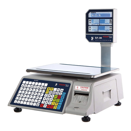
- Page 1 DLP-300 Label scale Service Manual DB SCALE SHANGHAI DIGITAL BALANCE ELECTRONIC CO., LTD...
-
Page 3: Table Of Contents
Catalog 1. Specifications ....................... 5 1.1 Introduction ......................5 1.2 Specifications and configuration ..............6 1.3 Environmental conditions and safety ............. 7 1.4 Positioning and horizontal instrument ............9 1.5 Power sockets and requirements ..............11 2.Classification ....................... 12 2.1 Overview of scales ..................12 2.2 Display and indicator .................. - Page 4 14.3 Exploded view of upper cover ..............84 14.4 Exploded view of bottom shell ..............85 14.5 Display and pole exploded view ..............86 14.6 Printer explosion diagram ................87 15.BOM ........................... 88...
-
Page 5: Specifications
We are sure that you will find that the DLP series scale will meet all your demanding needs. Print various reports through the printer of this device. You can also upload sales data through the wired network, wireless network, or 4G module of the device. -
Page 6: Specifications And Configuration
1.2 Specifications and configuration Specification DLP series 15lb 30lb 60lb Max range 0.01/0.02lb Min graduation 0.002/0.005lb 0.005/0.01lb 1/3000 Display resolution Internal resolution 1/60000 -9.995kg -2.999kg -5.998kg Max peeling LCD display; 4-digit tare weight; 5-digit weight; 6-digit unit price; 7-digit total price... -
Page 7: Environmental Conditions And Safety
1.3 Environmental conditions and safety 1)Please avoid the following harsh conditions · The temperature is below or above: -10 degrees to 40 degrees · Ungrounded outlet · Excessive vibration · Unstable or fragile surface · Where there is wind or fan running directly on the scale surface ·... - Page 8 4)Observe the following safety measures · Before you open the lid of the scale at any time, turn off the power switch of the scale and unplug the power plug. · The power plug of the scale should be tightly inserted into the power socket and properly grounded.
-
Page 9: Positioning And Horizontal Instrument
1.4 Positioning and horizontal instrument 1)Positioning The scale must be placed on a flat and stable surface. Keep the scale away from fans, ventilation systems or direct passages of strong air currents. Because of these air turbulences, they can be picked up by the very sensitive weighing platform of the scale and may cause incorrect weight readings. - Page 10 1.When the bubble is on the right, 2. When the bubble is on the left, turn the right adjustment foot clockwise or turn the left adjustment foot clockwise counterclockwise to adjust the left or counterclockwise to adjust the right adjustment foot. adjustment foot.
-
Page 11: Power Sockets And Requirements
1.5 Power sockets and requirements 1)Power outlet: AC 187V~242V 50Hz 1.5A Power: Max 90W Hole 3 Ground wire 2)Claim: (1)On electrical circuits, no high-noise devices (such as compressors, motors, etc.) can run on them. (2) Make sure that the power socket is wired correctly. If you are not sure about the working status of the power outlet, please contact an electrician for certification. -
Page 12: Classification
2.Classification 2.1 Overview of scales DLP series type LCD display 2.2 Display and indicator DLP series type 显 示... -
Page 13: Printer
Instructions Description Stable Arrow indicates when the weight is stable Arrow indicates at zero position Zero The arrow indicates when the network cable is plugged in Shift Letter case switch key Auto Automatic printing Save Save modified settings Prepack Pre-packaged R1-R3 trading model Report mode... -
Page 14: Communication
2.4 Communication · RS232 COM1 (serial port 1) ·ETHERNET (wired network port) ·USB (USB port) ·DRAWR (silver box mouth) · RS232 COM2 (serial port 2) ·Built-in WIFI 2.5 keyboard... -
Page 15: Introduction To A Subject
3.Introduction to a subject 3.1 Sealing method 3.2 Label paper installation · Label specifications: Paper roll outer diameter: 100mm; paper roll inner diameter: 40mm; paper roll width: 60mm · Printing area: Label width: 56mm; Label length: 120mm... - Page 16 · Remove label box 1. Open the roll paper box door on the left side of the electronic scale and turn it clockwise 45 degrees to open the buckle 2. Fasten the two grooves with your fingers and pull out the roll ·...
-
Page 17: Switch
3.3 Switch Turn on the power 1 .Make sure the power plug is inserted into the AC power outlet 2.Make sure nothing is on the weighing platform 3.Turn on the power switch to (1) position Turn off the power 1 .Do not turn off the power during printing 2.Do not turn off the power during operation 3.Turn off the power switch to the (0) position... -
Page 18: Calibration Mode
4.Calibration mode 4.1 Mode calibration ·You can click "TARE" to exit calibration without performing calibration. ·Long press the "ZERO" button, and at the same time click "3", "7", "5", "2", "9", "8" to open the permissions. ·Long press the "ZERO" button, and click "9", "8", "1", "1" at the same time to enter the calibration. - Page 19 ·The calibration is complete.
-
Page 20: Turn On The Calibration Switch
4.2 Turn on the calibration switch (1)Lift the bottom of the scale (2)Cut the seal line and remove the screw (3)Press the calibration button directly with your finger or other cylindrical tools. -
Page 21: Version View
5.Version view Version view can display all models of accessories used. ·Click "X" to view the next item. ·Click "ESC" to exit the view. Display... -
Page 25: Basic Operation
6.Basic operation Basic operations do not require elevated permissions, and users can modify them by themselves. *Long press "ZERO" and then click "1" "4" "1". *Click "X" to go to the next item. *Click "OVERRIDE" to enter the previous item. *Click "PRINT"... - Page 26 0. 2F5C5XS 7. 2F4C6XS 14. None 21. 2F4CXCD5XS 1. 1F6C5XS 8. 1F4C7XS 15. UDF1 22. 1F5CXCD5XS 2. 2F10CS 9. 1F5C6XS 16. UDF2 23. 2F5CXCD4XS 3. 2F5C5P5XS 10. 2F4C5X6PS 17. UDF3 24. 1F6CXCD4XS 4. 2F5C5X5PS 11. 2F4C6P5XS 18. UDF4 5. 1F6C5P5XS 12. 1F5C5X6PS 19. UDF5 6.
- Page 27 0 - 99 0. Control By PLU 7. G6 1. G0 8. G7 2. G1 3. G2 4. G3 5. G4 6. G5 0. Control By PLU 7. G6 1. G0 8. G7 2. G1 3. G2 4. G3 5. G4 6.
- Page 28 0. Hardware Control 7. 280 1. 40 8. 320 2. 80 9. 360 3. 120 4. 160 5. 200 6. 240 0. No 1. Yes 0. No 1. Yes 0. Lowest 1. Low 2. Normal 3. High 4. Highest 0 - 9999999 0 - 9999999...
- Page 29 0 - 9999999 0. No 1. Yes 0 - 60 0. 2F5C5XS 7. 2F4C6XS 14. None 21. 2F4CXCD5XS 1. 1F6C5XS 8. 1F4C7XS 15. UDF1 22. 1F5CXCD5XS 2. 2F10CS 9. 1F5C6XS 16. UDF2 23. 2F5CXCD4XS 3. 2F5C5P5XS 10. 2F4C5X6PS 17. UDF3 24. 1F6CXCD4XS 4.
- Page 30 0. No 1. Yes 0. No 1. Yes 0. No 1. Yes 0. No 1. Yes 1-32 0. No 1. Yes...
- Page 31 0. No 1. Yes 0. No 1. Yes 0. No 1. Yes 0. No 1. Yes 0. No 1. Yes...
- Page 32 0. No 1. Yes 0. No 1. Yes 0. No 1. Yes 1-60 0. EAN8/13 1. EAN128 2. CODE128 3. UPCA 4. UPCE 1-15...
- Page 33 1-15 0. NoPrint 1. TZ 2. HFWC 0. None 1. COM1 0. No 1. Yes 0. 10 Sec 1. 1 Min 2. 3 min 3. 10 min 4. 30 min 5. 60 min 0. No 1. Yes...
- Page 34 0. No 1. Yes 0. No 1. Yes 0. No 1. Yes 0. No 1. Yes 1-10 0. No 1. Yes...
- Page 35 0. +Check 1. -Check 0. No 1. Yes 0. Local Mode 1. Share Mode 1. Yes 0. No 1. Yes...
- Page 36 0. Lowest 1. Lower 2. Low 3. Normal 4. High 5. Higher 6. Higest 0. All black 1. Gradient 0. 숌竟櫓匡 1. English 2. Korea 3. 런竟櫓匡 0. Auto 1. Label Scale (No Printer) 2. Receipt Scale (No Printer) 0. No 1.
- Page 37 0. No 1. Yes 1000-20000...
-
Page 38: Function Setting
7.Function setting Function settings need to be elevated for maintenance personnel. *Long press "ZERO" and click on the numeric keypad "3""7""5""2""9""8". *Long press "ZERO" and click on the numeric keypad "1""0""1""3". *Long press "ZERO" and click on the numeric keypad "1""4""2". *Click "X"... - Page 39 0. None 1. Round 2. Round Down 3. Round Up 0. WT 1. QTY 2. Sum 0. WT 1. QTY 2. Sum 0. WT 1. QTY 2. Sum 0 - 9999999...
- Page 40 0. "Control By PLU" 6. $/t 1. $/Kg 7. $/lb 2. $/g 3. $/10g 4. $/100g 5. $/500g 0. No 1. Yes 0. No 1. Yes 0. Kg 1. g 2. t 3. lb 0. Disable 1. Normal 2. Lock 3.
- Page 41 0. No 1. Yes 0. Disable Auto Power Off 6. 18 Minute 1. 3 Minute 7. 21 Minute 2. 6 Minute 3. 9 Minute 4. 12 Minute 5. 15 Minute 0. 9600 1. 19200 0. No 1. Yes 0. 600 6.
- Page 42 0. No 1. Yes 0. No 1. Yes 0. No 1. Yes 0. No 1. Yes 0. 40ms 1. 100ms 2. 200ms 3. Control By Pc 0. Start CHK Net +” 1. Start CHK Net - 2. Start CHK Net - 3.
- Page 43 0. No 1. Yes 0. ±2%FS 1. ±4%FS 2. ±10%FS 3. No Limit 0. ±2%FS 1. ±4%FS 2. ±10%FS 3. No Limit 0. No 1. Yes 0. No 1. Yes 0. No 1. Yes 0. No 1. Yes...
- Page 44 0. <50%FS 1. <100%FS 0. No 1. Yes 0. Net WT>5d 1. Nwt WT>5d GWT>21d 0. No 1. Yes 0. UF When Net<-2d 1. UF When GWT<-2d 2. Show Negative Weight 3. Invalid Value 0. No 1. Yes 0. No 1.
- Page 45 0. No 1. Yes 0. No 1. Yes 0. No 1. Yes 0. No 1. Yes 0. 50 6. 350 12. 650 1. 100 7. 400 13. 700 2. 150 8. 450 14. 750 3. 200 9. 500 15. 800 4.
- Page 46 0. kg 1. lb 0. 3.00-4.00 1. 2.00-2.99 2. 1.00-1.99 3. 0.4-0.99 0. Open Max WT 1. Fix Max WT 0. Single Range 1. Dual Range 0. 6kg 1. 15kg 2. 30kg 3. Invalid Value 0. Dual Range Only Net 1.
- Page 47 0. Object 1. Full Range 0. 1 6. 100 1. 2 7. Invalid Value 2. 5 3. 10 4. 20 5. 50 0. 1000d 6. 4000d 12. 15000d 1. 1250d 7. 5000d 13. 20000d 2. 1500d 8. 6000d 14. Invalid Value 3.
-
Page 48: Network Settings
8.Network settings Network settings can modify the network IP or other related content. *Long press "ZERO" and click on the numeric keypad "1""1""2". *Click "X" to go to the next item. *Click "OVERRIDE" to enter the previous item. *Click "PRINT" to enter internal modification or save the modified content. Mode 112 Spec Display... -
Page 56: Printer Settings
9.Printer settings The printer settings can modify the printing paper or the related functions of the machine. *Long press "ZERO" and click on the numeric keypad "1""1""3". *Click "X" to go to the next item. *Click "OVERRIDE" to enter the previous item. *Click "PRINT"... - Page 57 Done. • Press the Feed button to feed or print a second label to change the print start position. • The default label printing position is 64 points from the bottom • Unit switching: 8 points = 1mm, 64 points = 8mm •...
-
Page 58: Mode
10.X Mode The product value can be viewed in X mode. Display... -
Page 59: Z Mode
11.Z Mode Z Mode can clear the content. Display... -
Page 63: Repair And Replacement Parts
12.Repair and replacement parts... -
Page 64: Remove The Upper Cover
12.1 Remove the upper cover *Any of the following operations need to turn off the power of the electronic scale and unplug the power cord. · Steps to remove the upper cover: 1)Take off the weighing pan, as shown: 2)Unscrew the 4 screws on the "aircraft frame" as shown in the picture:... - Page 65 3)Unscrew the 6 screws at the bottom, as shown: 4) When removing the upper cover, you need to move forward to avoid the print port and disconnect the keyboard cable, as shown in the figure: 5)The upper cover is removed.
-
Page 66: Open The Bottom Plate
12.2 Open the bottom plate *Any of the following operations need to turn off the power of the electronic scale and unplug the power cord. · Steps to remove the bottom plate: 1)Unscrew the 8 screws at the bottom, as shown: 2)After unscrewing the screw, the inside is as shown in the figure:... -
Page 67: Load Cell And Motherboard Replacement
12.3 Load cell and motherboard replacement *Any of the following operations need to turn off the power of the electronic scale and unplug the power cord. · Load cell replacement steps: 1)Open the bottom plate according to step 12.2, as shown in the figure: 2)The wire sequence of the load cell can be seen as shown in the figure. - Page 68 If the load cell is replaced, re-welding is required. Note: Must re-calibrate! ·Motherboard replacement steps: 1)Disconnect different wiring harnesses, as shown: 2)Unscrew 6 screws, as shown:...
-
Page 69: Print Driver Board Replacement
Note: The load cell needs to be re-welded and must be re-calibrated! 12.4 Print driver board replacement *Any of the following operations need to turn off the power of the electronic scale and unplug the power cord. · Print driver board replacement steps: 1)Open the upper cover according to step 12.1, as shown in the figure:... - Page 70 3)Disconnect different wiring harnesses, as shown:...
- Page 71 4)Unscrew 4 screws, as shown: 5)After disassembly, follow the reverse steps to install the print driver board.
-
Page 72: Printer Mechanism Replacement
12.5 Printer mechanism replacement *Any of the following operations need to turn off the power of the electronic scale and unplug the power cord. · Printer mechanism replacement steps: 1)Open the upper cover and unscrew the two screws and wire harness according to step 12.1, as shown in the figure:... -
Page 73: Power Board Replacement
12.6 Power board replacement *Any of the following operations need to turn off the power of the electronic scale and unplug the power cord. · Power board replacement steps: 1)Open the bottom plate according to step 12.2 and disconnect the two wire harnesses, as shown in the figure:... -
Page 74: Interface Board Replacement
12.7 Interface board replacement *Any of the following operations need to turn off the power of the electronic scale and unplug the power cord. · Interface board replacement steps: 1)Unscrew 2 screws as shown in the picture: 2)Unplug the cable and replace it with a new interface board, as shown in the figure:... -
Page 75: Keyboard Board Replacement
12.8 Keyboard board replacement *Any of the following operations need to turn off the power of the electronic scale and unplug the power cord. · Keyboard board replacement steps: 1)Unscrew 6 screws and two wire harnesses, as shown in the picture: 2)Replace the keyboard after the operation is complete. -
Page 76: Print Head Replacement
12.9 Print head replacement *Any of the following operations need to turn off the power of the electronic scale and unplug the power cord. · Print head replacement procedure: 1)Turn on the printer, turn the print head switch, take out the printer: 2)Unscrew the external screws of the print head, as shown in the figure:... - Page 77 3)Unscrew 2 screws, as shown: 4)Pull out the metal plate of the print head and unscrew 2 screws, as shown in the picture:...
- Page 78 5)Unplug the 2 wires to replace the print head, as shown in the figure:...
-
Page 79: Display Board Replacement
12.10 Display board replacement *Any of the following operations need to turn off the power of the electronic scale and unplug the power cord. · Display board replacement steps: 1)Pull down the shell sleeve vertically, as shown in the figure: 2)From the side of the shell, both hands move outward at the same time, as shown in the picture:... - Page 80 3)Unplug the old display board harness and unscrew 8 screws to replace the new display board:...
-
Page 81: Schematic Diagram
13.Schematic diagram 13.1 Connection Diagram Print Head Print head switch CN 7 Main motor Peel sensor Label sensor Print driver board Monitor CN 5 CN153 CN150 标 定 开 关 无 线 天 线 M o t h e r b o a r d SPAN-SW CN152 CN156 CN151... -
Page 82: Exploded View
14.Exploded view 14.1 Schematic diagram of the overall explosion of the scale... -
Page 83: Explosion Diagram Of Sensor Assembly And Bottom Case
14.2 Explosion diagram of sensor assembly and bottom case... -
Page 84: Exploded View Of Upper Cover
14.3 Exploded view of upper cover... -
Page 85: Exploded View Of Bottom Shell
14.4 Exploded view of bottom shell... -
Page 86: Display And Pole Exploded View
14.5 Display and pole exploded view... -
Page 87: Printer Explosion Diagram
14.6 Printer explosion diagram... -
Page 88: Bom
15.BOM Category Part drawing No. Material Quantity Picture PLATTER-TOP_7 SUS304 BRACKET-DISP-SUPT- Galvaniz SMALL_1 ed sheet LOADCELL-SUPT-BTM- SPCC NEW_1 BRACKET-MB-COVER_ SPCC 7-SHAPED PATCH SPCC BRACKET-ITFC-CONN_ SPCC 18_1 BASE-POWER BOARD SPCC Sheet metal BRACKET-DOOR_1 SPCC BRACKET-MAIN_8 SPCC PRT-CTRL-BOX_1 SPCC PRT-CTRL-BOX_2 SPCC BRACKET-PRT-REAR_1 SPCC BRACKET-GEAR-PAPE SPCC... - Page 89 CUTTER_1 BRACKET-PRT_4 SPCC BRACKET-ADJUST_1 SPCC BRACKET-MOTO-ADJU SPCC ST_1 BRACKET-PAPER-RCP BRACKET-PAPER-RCP BRACKET_PEAR_21 SUS304 DISPENSER_13 SUS304 BRACKET-RCPT-STOP SUS304 BRACKET-RCPT-STOP SUS304 BASE-LABEL-PRT ADC-12 AL-SUPT-POLE-BTM-BI ADC-12 Aluminu LOADCELL-SUPT_3 ADC-12 products LOADCELL-SUPT-UP_2 ADC-12...
- Page 90 ROLLER-SUPT_1 ADC-12 AL-8-SUPT_2 Zinc alloy BRACKET-PRT-RT-SUP Zinc alloy BRACKET-PRT-BB_1 Zinc alloy AL-PIPE-P DOOR-PRT_8 29-COVER-PRT-BTM-0 90907_17 COVER-POLE-BTM-RC PT_8 CASE-DISP-SMALL-FR CASE-DISP-SMALL-RE Plastic HUAN_POLE_DIS1_4 22-TOP-COVER-P-0909 07_3 20-FRONT-PANEL-POL E-090907_3 18-PRT-COVER090907_...
- Page 91 BOSS-TONG-XW_1 BUSS-3_1 BUSS-3_2 BUSS-3_3 GEAR-PAPER-RCPT-09 0223 BELT-STOP-PAPER GEAR-ROLLER_1 BELT-STOP-ROLLER_1 BUSS-MOTO-GEAR_1 BELT-STOP-MOTO_1 GEP-SENSOR-HOUSIN PAPER-RCPT-ROLL-1_ CASE-PAPER-CHANGE PAPER-RCPT-A...
- Page 92 COVER-ROLL CASE-AA_1 CASE-PAPER-IN-STOP COVER-STOP BRACKET-PAPER-A_12 _010 PRT_CSYS_DEF GUARD_10 PLUG COLLOR_4 Carbon steel SPRING__R SPRING__L Axle car SHOUZHIYAHUANG parts AXIS-ADJUST-CT_1 AXIS-PRT-RT-CT_1 Carbon steel...
- Page 93 AXIS-PAPER-RCPT AXIS-THROUGH AXIS SUS304 AXIS_010 SUS304 ROLLER SUS304 RUBBER LINE CARD ( 80-85 RUBBER-PLATTER-A2- 090905_1 ( 80-85 Rubber parts RUBBER-PLATTER-A1- 090905_1 ( 80-85 RUBBER MAT Rubber mold CABLE WIRE-00010-01 CABLE_WIRE_00510-01 CABLE_WIRE_00513-01 Wire harness CABLE_WIRE_00514-00 CABLE WIRE-00435-01...
- Page 94 FLAT RIBBON CABLE 26PIN CABLE WIRE-00216-00 CABLE_WIRE_00511-02 WIRE-00023-00 CABLE WIRE-00013-00 CABLE WIRE-00014-01 WIRE-000031-02 WIRE-000030-01 WIRE-00034-01 WIFI LINE POWER CORD 2.5M SINGLE HEAD 8059-0016-M 8059-0015-M Cover 8059-0100-M...
- Page 95 8059-0099-M H015-415 8059-0065-M H015-453 8059-0101-K TWO-IN-ONE MOTHERBOARD PCB-0009-01 PCB-0060-08 PCB-0061-07 PCB-0055-02 Circuit board PCB-0045-03 PCB00-0052-09 PRT-OPEN-SENCER_1 STSPCB00-0003-02...
- Page 96 STSPCB00-0002-02 LCD SCREEN (822, 821) INNER BOX (600*505*375) OUTER BOX PEARL COTTON MANUAL 1 MANUAL 2 PLASTIC PACKAGE OPENING X600X0.05 PACKAGE SCALE OPENING X360X0.05 PACKAGE DISPLAY NAMEPLATE 1-LEG-NEW-090907_3 Rubber HINGE Other FDS-80B...
- Page 97 STANDARD PARTS FILTER-LEVEL_2 XITIESHI-DOOR_4 LOADCELL-NEW MAGNETIC RING ON-OFF-KEY FUSE HOLDER POWER CORD CARD MAOZHAN-A_1 42PM048L9-00702 PRINT HEAD BELT_2M_320...
- Page 98 数 衡 DB SCALE 上海数衡电子有限公司 地址:上海市青浦区崧秀路 788 号 电话:021-59757333 传真:021-69758439 邮编:201703...
Need help?
Do you have a question about the DLP Series and is the answer not in the manual?
Questions and answers