Table of Contents
Advertisement
Quick Links
Advertisement
Table of Contents

Related Manuals for Newport ILX Lightwave LDM-4405


Summary of Contents for Newport ILX Lightwave LDM-4405
- Page 1 User’s Guide TO-Can Laser Diode Mount LDM-4405 700415 May 2021...
-
Page 3: Table Of Contents
T A B L E O F C O N T E N T S ABLE OF ONTENTS Table of Contents ......... . . i List of Figures and Tables . -
Page 4: Table Of Contents
T A B L E O F C O N T E N T S Temperature Control and Condensation ......12 Thermoelectric Temperature Control . -
Page 5: List Of Figures And Tables
L I S T O F F I G U R E S A N D T A B L E S IST OF IGURES AND ABLES Figure 1.1 Exploded View of the LDM-4405 ....2 Figure 1.2 Rear View of the LDM-4405 . - Page 6 L I S T O F F I G U R E S A N D T A B L E S LDM-4405...
-
Page 7: Safety And Warranty Information
AFETY AND ARRANTY NFORMATION The Safety and Warranty Information section provides details about cautionary symbols used in the manual, safety markings used on the instrument, and information about the Warranty including Customer Service contact information. Safety Information and the Manual Throughout this manual, you will see the words Caution and Warning indicating potentially dangerous or hazardous situations which, if not avoided, could result in death, serious or minor injury, or damage to the product. -
Page 8: Safety Symbols
S A F E T Y S Y M B O L S AFETY YMBOLS This section describes the safety symbols and classifications. Technical specifications including electrical ratings and weight are included within the manual. See the Table of Contents to locate the specifications and other product information. -
Page 9: Warranty
W A R R A N T Y ARRANTY ILX LIGHTWAVE CORPORATION warrants this instrument to be free from defects in material and workmanship for a period of one year from date of shipment. During the warranty period, ILX will repair or replace the unit, at our option, without charge. -
Page 10: Comments, Suggestions, And Problems
Fax ..........(406) 586-9405 On the web at: ..... . www.newport.com/b/ilx-lightwave... -
Page 11: Introduction
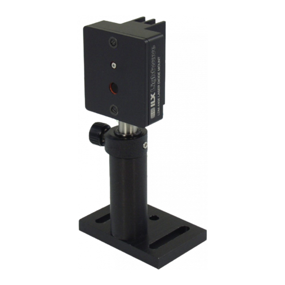
C H A P T E R NTRODUCTION This manual describes the LDM-4405 Laser Diode Mount and explains its operation. Information is also provided to assist in customizing this mount to satisfy specific laser mounting needs. This chapter provides an overview of the LDM-4405 Laser Diode Mount, and contains general information and specifications. - Page 12 I N T R O D U C T I O N C H A P T E R Product Overview Figure 1.1 illustrates the LDM-4405 with cover/clamp removed, revealing the laser mounting plate and internal PCB. Figure 1.2 shows the rear of the mount, including connectors and switches.
-
Page 13: Specifications
I N T R O D U C T I O N C H A P T E R Specifications Specifications Laser Packages Styles Supported 5.6 mm and 9 mm TO-can, Type 1 Lead Length 5-20mm Maximum Laser Current 500 mA Input Connectors Current Source 9-pin D-Sub, female... - Page 14 I N T R O D U C T I O N C H A P T E R Specifications LDM-4405...
-
Page 15: Operation
C H A P T E R PERATION This chapter describes the electrical connection and mounting of laser diodes. Configuration options for the LDM-4405 for different device pin outs are also discussed. Mount Configuration The LDM-4405 mount is designed for Type 1 TO-can laser diodes containing a laser diode pin, a photodiode pin, and a center common pin. - Page 16 O P E R A T I O N C H A P T E R Mount Configuration Table 2.1 Pinout Combinations and Configurations of Laser Diodes - LDM-4405 For example, if the laser diode pin on your device is cathode (-) and the photo diode pin is anode (+), you would select the "-"...
-
Page 17: Laser Diode Mounting
O P E R A T I O N C H A P T E R Laser Diode Mounting Laser Diode Mounting Laser diodes are extremely susceptible to damage caused by electrostatic discharge and surge currents. To avoid early failure or damage to the device, workers and work benches must be grounded at all times when handling or working with laser diodes. - Page 18 O P E R A T I O N C H A P T E R Laser Diode Mounting Figure 2.2 Laser Diode Insertion The one-piece cover/clamp accommodates both 5.6 mm and 9 mm TO-can devices. The clamp uses an O-ring to apply preload onto the device for good thermal connection to the laser mounting plate.
- Page 19 O P E R A T I O N C H A P T E R Laser Diode Mounting Figure 2.3 Mount with Laser and Cover/Clamp Installed 05_21 LDM-4405 ...
-
Page 20: Current Sources And Current Measurements
O P E R A T I O N C H A P T E R Current Sources and Current Measurements Current Sources and Current Measurements Operate the LDM-4405 Laser Diode Mount using an appropriate ILX Lightwave current source and temperature controller. Operation with other current sources or temperature controllers is also possible, provided that the correct wiring is observed (refer to Figures 2.4 and 2.5). - Page 21 O P E R A T I O N C H A P T E R Current Sources and Current Measurements Figure 2.5 LDM-4405 TE Module Cable Pinouts Do not exceed the specified maximum drive current of the laser. If you are using an ILX Lightwave current source, or any other current source which has an adjustable limit setting, be sure to set the current limit to a safe level for your laser.
- Page 22 O P E R A T I O N C H A P T E R Temperature Control and Condensation Temperature Control and Condensation Thermoelectric Temperature Control The LDM-4405 contains a single solid-state thermoelectric (TE) module. The TE module is located between the laser plate and the housing heat sink. This Peltier heat pump is capable of heating and cooling the laser diode when supplied with current from an appropriate temperature controller.
- Page 23 C H A P T E R AFETY Laser diodes used with the LDM-4405 Laser Diode Mount may emit infrared radiation which is invisible to the human eye. Extreme care must be taken to prevent the beam from being viewed either directly or through external optics or mirrors. Remove rings, jewelry, and other reflective materials when working with lasers.
- Page 24 S A F E T Y C H A P T E R LDM-4405...
Need help?
Do you have a question about the ILX Lightwave LDM-4405 and is the answer not in the manual?
Questions and answers