Table of Contents
Advertisement
Quick Links
Advertisement
Table of Contents

Related Manuals for Newport 708 Series


Summary of Contents for Newport 708 Series
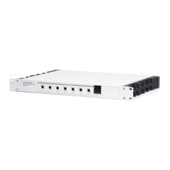
- Page 1 (217) 352-9330 | Click HERE Find the Newport 708 at our website:...
- Page 2 Model 708 8-Channel Butterfly Telecom Laser Diode Mount User's Manual Artisan Scientific - Quality Instrumentation ... Guaranteed | (888) 88-SOURCE | www.artisan-scientific.com...
- Page 3 Printed 17-Mar-00 Newport Corporation, Irvine, California, has been certified compliant with ISO 9002 by the British Standards Institution. Corporate Headquarters Canada Italy Netherlands Taiwan R.O.C. Newport Corporation Telephone: 905-567-0390 Telephone: 02-924-5518 Telephone: 030-6592111 Telephone: 2-2769-9796 1791 Deere Avenue Facsimile: 905-567-0392...
- Page 4 Limited Warranty Newport warrants that this product will be free from defects in materials and workmanship for a period of two years from the date of shipment. If any such product proves defective during the applicable warranty period, Newport, at its option, either will repair the defective product with charge for parts and labor or will provide a replacement in exchange for the defective product.
- Page 5 Artisan Scientific - Quality Instrumentation ... Guaranteed | (888) 88-SOURCE | www.artisan-scientific.com...
-
Page 6: Table Of Contents
Table of Contents General Information _____________________________________________________ 1 Introduction __________________________________________________________________ 1 Model 708 Laser Diode Mount ___________________________________________________ 1 Safety Terms__________________________________________________________________ 2 General Warnings and Cautions _________________________________________________ 2 Model 708 Laser Diode Mount Specifications_______________________________________ 3 Butterfly Telecom Laser Diode Mount Use____________________________________ 5 Introduction __________________________________________________________________ 5 Installation ___________________________________________________________________ 5 2.2.1... - Page 7 Table of Figures Figure 1 – Model 708 8-Channel Butterfly Telecom Laser Diode Mount __________________________________1 Figure 2 – Model 708 8-Channel Butterfly Telecom Laser Diode Mount Front Panel ________________________6 Figure 3 – Model 708 Laser Diode Mount Rear Panel ________________________________________________6 Figure 4 –...
-
Page 8: General Information
FC/PC, FC/APC, SC/PC, SC/APC, or ST fiber connectors. The Model 708 mount offers an easy-to-use platform that is compatible with all of Newport's benchtop laser diode instrumentation and with Newport's test and measurement and burn-in rack type systems. -
Page 9: Safety Terms
Chapter 4 of this manual. WARNING Any use of the Model 708 not specified by Newport Corporation, or failure to comply with precautions or specific warnings elsewhere in this manual violates safety standards of design, manufacture, and intended use of this equipment. -
Page 10: Model 708 Laser Diode Mount Specifications
9 pounds (4.1 kilograms) NOTE: In accordance with ongoing efforts to continuously improve our products, Newport Corporation reserves the right to modify product specifications without notice and without liability for such changes. Artisan Scientific - Quality Instrumentation ... Guaranteed | (888) 88-SOURCE | www.artisan-scientific.com... - Page 11 Artisan Scientific - Quality Instrumentation ... Guaranteed | (888) 88-SOURCE | www.artisan-scientific.com...
-
Page 12: Butterfly Telecom Laser Diode Mount Use
Introduction The Model 708 8-Channel Butterfly Telecom Laser Diode Mount is designed for use with Newport Corporation controller and rack systems. The following chapter provides information for safely and effectively setting up and using the Model 708 Butterfly Package mount. -
Page 13: Front Panel Familiarization
Chapter 2 Butterfly Telecom Laser Diode Mount Use Front Panel Familiarization Described below is the Model 708 Laser Diode Mount front panel as shown in Figure 2 – Model 708 8-Channel Butterfly Telecom Laser Diode Mount Front Panel below. Figure 2 – Model 708 8-Channel Butterfly Telecom Laser Diode Mount Front Panel 1. -
Page 14: Laser Diode Protection Requirements
(transients). Damage can result in reduced output power, shift in threshold current, changes in beam divergence, and ultimately failure to lase (LED-like output only). Newport precision current sources and controllers offer the most advanced laser protection features available, including power line filters, clamping current limits, and slow-start-up circuits. -
Page 15: Figure 4 - Butterfly Laser Diode Mounting
Chapter 2 Butterfly Telecom Laser Diode Mount Use Mount the laser diode devices according to the following procedure: 1. Using a cross-slotted screwdriver, remove the six (6) screws from the Model 708 top case cover. 2. Starting with position 1, open the laser diode pin clamps for the mount. 3. -
Page 16: Figure 5 - Laser Diode Package Pin Clamps Closed
Chapter 2 Butterfly Telecom Laser Diode Mount Use 7. Close the laser diode pin clamps on the laser diode device until the clamps lock. The clamps should lock firmly over the diode pins. Mounted Butterfly Style Laser Diode Package Closed Pin Clamps Figure 5 –... -
Page 17: Butterfly" Style Laser Diode Device Mounting Base Plate Height Adjustment
Chapter 2 Butterfly Telecom Laser Diode Mount Use "Butterfly" Style Laser Diode Device Mounting Base Plate Height Adjustment The Model 708 allows the user to adjust the height of the laser diode device mounting plate in the fixture to accommodate different height and style butterfly laser diode packages. -
Page 18: 8-Channel Butterfly Telecom Laser Diode Mount Connections
The "scramble" configuration boards available for the Model 708 laser diodes allow the user to change the configuration for the communications connector. Two different configuration boards are available through Newport Corporation. The pin assignments for each configuration board are listed in Table 3 – Configuration Board Pin Assignments. -
Page 19: Configuration Board Identification
Chapter 2 Butterfly Telecom Laser Diode Mount Use 2.8.2.1 Configuration Board Identification Table 2 – Configuration Board Identification provides information that can be used to order or identify a configuration board for the Model 708 Laser Diode Mount. The Dash Number is used for ordering purposes. The Model Number is used to identify the board layout. -
Page 20: Maintenance
C H A P T E R Maintenance Introduction Module specific calibration can be found in the module's manual. No calibration is required on the mainframe. Do not attempt to remove the cover of the instrument! General Cleaning The Model 708 is designed for easy and reliable usage. Regular cleaning of the instrument and connectors will help to maintain the appearance and trouble-free operation of the Model 708. -
Page 21: Connector End Face Preparation
The typical insertion loss of the FC connector is around 0.3 dB. Drilled-out, metallic FC connectors, having insertion losses of > 1 dB, are being used with Newport's large-core (> 140 µm) fibers. SC – The more recently introduced SC connector is becoming increasingly popular in single-mode fiber optic telecom and analog CATV, field deployed links. -
Page 22: Cleaning Fiber Optic Connectors
Chapter 3 Maintenance SPC Polish – In the Super PC (SPC) polish, an extended polishing cycle enhances the surface quality of the connector, resulting in back reflections of -40 to -55 dB. This polish is used in high-speed, digital fiber optic transmission systems. APC Polish –... - Page 23 Chapter 3 Maintenance 7. Using a new clean cotton swab or lens paper with pure isopropyl alcohol, clean the fiber optic tip. 8. Using a clean dry cotton swab or lens paper, immediately dry the wet fiber optic tip. 9. Using clean, dry compressed air, blow across the end face of the fiber optic tip at a distance of approximately 6 to 8 inches away.
-
Page 24: Factory Service
Instrument serial number (on rear panel) Description of the problem If the instrument is to be returned to Newport Corporation, you will be given a Return Materials Authorization (RMA) number, which you should reference in your shipping documents as well as clearly marked on the outside of the shipping container. - Page 25 Artisan Scientific - Quality Instrumentation ... Guaranteed | (888) 88-SOURCE | www.artisan-scientific.com...
- Page 26 Service Form Newport Corporation USA Office: 949/863-3144 FAX: 949/253-1800 Name RETURN AUTHORIZATION # Company (Please obtain prior to return of item) Address Country Date P.O. Number Phone Number Item(s) being returned: Model # Serial # Description Reason for return of goods (please list any specific problems)
- Page 27 Where is measurement being performed? (factory, controlled laboratory, out-of-doors, etc.) What power line voltage is used? Variation? Frequency? Ambient Temperature? Any additional information. If the user has made special modifications, please describe below. Artisan Scientific - Quality Instrumentation ... Guaranteed | (888) 88-SOURCE | www.artisan-scientific.com...
Need help?
Do you have a question about the 708 Series and is the answer not in the manual?
Questions and answers