
Related Manuals for Thies CLIMA DLU

Summary of Contents for Thies CLIMA DLU
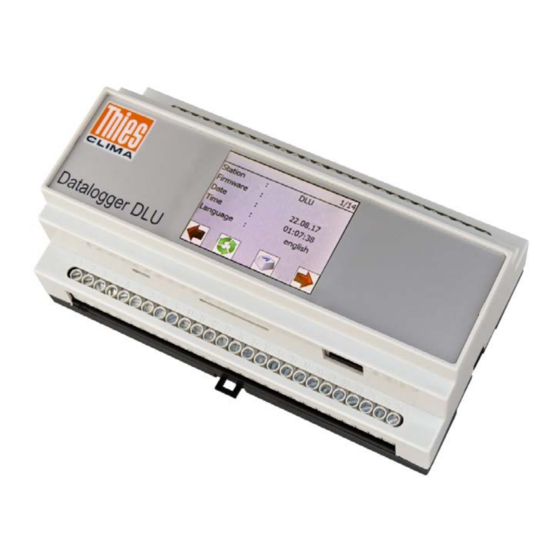
- Page 1 Data logger DLU (E) Instructions for Use 9.1711.10.0x0 Doc. No. 021821/08/21 T H E W O R L D O F W E A T H E R D A T A...
- Page 2 Safety Instructions • Before operating with or at the device/product, read through the operating instructions. This manual contains instructions which should be followed on mounting, start-up, and operation. A non-observance might cause: - failure of important functions - endangerment of persons by electrical or mechanical effect - damage to objects •...
-
Page 3: Table Of Contents
4.2.2 Selection Mode ....................21 4.2.3 Editing Mode .....................22 Switch off Data Logger .................... 23 Loading Configurations from SD Card ..............25 Network Module (Data logger DLU E 9.1711.10.010) ..........26 4.5.1 General ......................26 4.5.2 Installation requirements ...................27 4.5.3 Set up Network Access ..................27 4.5.3.1... - Page 4 7.1.1 Structure of the Commands (requests) ..............56 7.1.2 Structure of the Response Telegram ..............56 7.1.3 Optional framing with 16Bit CRC ...............57 Commands ......................58 7.2.1 Command ArchID....................59 7.2.2 Command BP_COM1 ..................59 7.2.3 Command BP_COM2 ..................60 7.2.4 Command BP_USB ..................60 7.2.5 Command BR_COM1 ..................61 7.2.6 Command BR_COM2 ..................61...
- Page 5 IP-Settings ....................... 81 WIFI ......................... 82 NTP ......................... 83 SFTP ........................84 9.10 Date......................... 85 9.11 Data Download Password ..................85 9.12 Data Upload ......................86 9.13 Internet Cloud Connection ..................87 9.14 Info .......................... 88 10 THIES Cloud and THIES Cumulus .................89 11 Technical Data .......................91 12 Dimensioned Drawing ....................94 13 Wiring Diagram ......................95...
-
Page 6: Device Design
1 x Wiring diagram (order-related connection diagram: Data logger, Measuring transducer etc.) The instructions for use of the DLU are available for download under the following link: https://www.thiesclima.com/db/dnl/9.1711.10.0x0_Data logger-DLU_eng.pdf © Adolf Thies GmbH & Co. KG · Hauptstraße 76 · 37083 Göttingen · Germany 021821/08/21 Tel. -
Page 7: Application / Setup Of The Data Loggers
2 Application / setup of the Data loggers You have the option of operating the DLU E data logger in different ways. The following illustration is intended to provide an overview. Figure 1: Application options © Adolf Thies GmbH & Co. KG · Hauptstraße 76 · 37083 Göttingen · Germany 021821/08/21 Tel. -
Page 8: Figure 2: Layout Plan Of The Connections
The Data logger DLU is a complete measurement system for the acquisition, processing and saving of the measurement data from a wide variety of sensors, like e.g. Precipitation sensors with pulse outputs. Sensors with measuring resistance (e.g. Pt100 temperature sensor). -
Page 9: Table 2: Terminal Allocation
Following table shows the allocation of the connection terminals of the Data logger: Terminal Signal Supply 24Vac/dc 12V accumulator 12V solar Sensor supply PT100 0-1V humidity Supply + Analogue IN1 Supply - Supply + Analogue IN2 Supply - Supply + Analogue IN3 Supply - GND / AGND... - Page 10 The installation of this rail-mounted device (9 HP, horizontal pitches) is envisaged in distributor systems with common 35mm mounting rails (DIN rail) and covers with a 45mm cut-out measurements. The wiring is connected via jack terminals in the lower and upper device section (see Figure 1).
-
Page 11: Installation
Install a 35mm mounting rail with a length of at least 9HP (157mm) at the installation location. • Place the data logger DLU on the mounting rail that the top edge of the rail grips into the corresponding groove of the data logger DLU. •... -
Page 12: Electrical Installation
3.3 Electrical Installation 3.3.1 Wiring In order to build a low-noise (i.e. EMC-compliant) measurement system, the data and measuring lines must be shielded. Thorough earthing of the shielding is to be ensured. Depending on local conditions, a distinction is to be made between: •... -
Page 13: Accumulator
The functional earth of the Data logger DLU (terminal 52) is to be connected with a 2.5mm² cable (L <6cm) to an earthed shield rail or mounting rail. For potential equalisation we recommend the use of the shortest possible cable (≤1m) with a cross-section of at least 6mm²... -
Page 14: Solar Panel
3.3.3 Solar Panel Electrical Connection: The connection of the optional 12V solar panels is to be carried out in accordance with the wiring diagram (see chapter 13). We recommend that the solar panel be earthed to protect it against excess voltages. The integrated 12V solar controller carries out temperature-guided control for optimal charging of the accumulator. -
Page 15: Potential-Free Switch Outputs
3.3.4 Potential-free Switch Outputs The Data logger possesses 2 potential-free switch outputs that can be switched dependent on the configuration. Digital OUT 1 Terminal 46 Configurable control Terminal 47 Digital OUT 2 Terminal 44 Configurable control Terminal 45 Figure 5: Potential-free switch outputs The switch outputs are equipped with a current limit of approx. -
Page 16: Rs485 Interfaces (Com1 / Com2)
3.3.5 RS485 Interfaces (COM1 / COM2) The Data logger possesses 2 full/half-duplex-capable RS485 interfaces that are controlled independently from the configuration. COM 1 Terminal 39 Terminal 41 Terminal 40 Terminal 42 Terminal 41 Terminal 42 Terminal 43 Terminal 43 COM 2 Terminal 34 Terminal 34 Terminal 35... -
Page 17: Measuring Transducer Supply
3.3.6 Measuring Transducer Supply The Data logger possesses various outputs for the supplying of connected measuring transducers that are controlled dependently on the configuration. Terminal Signal 3.3V or 5V or 12V 3,3V or 5V or 12V 3,3V or 5V or 12V Table 3: Measuring transducer supply For the permissible load on the supplies, see technical data. -
Page 18: Display Options
Symbol (Button) Meaning Shut down / reset of the Data logger Page back Page forward Activating selection/editing mode Push cursor position left Shift cursor position to the right Increment value at cursor position Decrement value at cursor position End selecting/editing mode End editing mode End selection/editing mode without saving Delete characters at the cursor (only when editing character... -
Page 19: Adjusting Parameters
Total number Current page of pages Line 1 1/14 Station DLU1 Firmware : V01.01 Date 29.05.17 Time 16:34:00 Language : German Lower area with control keys Figure 7: Dialogue page 1 The keys for flicking forwards and backwards are located in the lower part of each dialogue page. -
Page 20: Password Dialogue
4.2.1 Password Dialogue Before the “selection mode” can be activated, the corresponding password must be set. The following figure shows the password dialogue. 1/14 Station DLU1 Firmware : Password input: V01.01 Date 29.05.17 00000234 Time 16:34:00 Cancel Language : German Figure 8: Password dialogue The password is input with the 4 keys below the input field (“<”, “^”, “v”, “>”) and must be confirmed by pressing the “Ok”... -
Page 21: Selection Mode
4.2.2 Selection Mode The following figure shows the selection mode for the 1st dialogue page. 1/14 Station DLU1 Firmware : V01.01 Date 29.05.17 Time 16:34:00 Language : German Figure 10: Selection mode In the selection mode, one can move between the editable entries by pressing the keys Pressing one of the keys takes one out of the selection/editing mode. -
Page 22: Editing Mode
4.2.3 Editing Mode The following figure shows the editing mode for the entry “Station” on the 1st dialogue page. 1/14 Station DLU1 Firmware : V01.01 Date 29.05.17 Time 16:34:00 Language : German Figure 11: Edit mode In the editing mode, the content for the current cursor position can be changed by pressing the keys for numerical values, this increments / decrements the selected position and for texts it moves forwards / backwards through a list with the available ASCII characters. -
Page 23: Switch Off Data Logger
Figure 13: Reset key After pressing the key “Reset”, the LINUX system in the Data logger is shut down. This is displayed with the information box “Shutdown DLU”. © Adolf Thies GmbH & Co. KG · Hauptstraße 76 · 37083 Göttingen · Germany 021821/08/21 Tel. -
Page 24: Figure 14: Information Box "Shutdown Dlu
Language : German Figure 14: Information box "Shutdown DLU The shutting down lasts approx. 15s, then a dialogue appears with the possibility of carrying out a restart of the Data logger. In this state, the Data logger can be separated from the supply. -
Page 25: Loading Configurations From Sd Card
1/14 Station DLU1 Reset data logger ? Firmware : V01.01 Datum 29.05.17 Zeit 16:34:00 Sprache : deutsch Figure 15: Dialogue “Reset yes” Pressing the key “yes” carries out a restart of the Data logger. Attention: Switching off the supply without shutting down the Data logger can lead to damage and failure of the network interface! 4.4 Loading Configurations from SD Card If an SD card in the Data logger and contains a configuration file, the "Import"... -
Page 26: Network Module (Data Logger Dlu E 9.1711.10.010)
The data logger DLU E 9.1711.10.010 is equipped with an ethernet module. The module offers the following options: 1. Simultaneous access by several users to the DLU via Ethernet via user logins 2. Access via Telnet, SFTP und WEB 3. Use all commands chapter 7.2 via Telnet 4. -
Page 27: Installation Requirements
You can find out from your administrator whether your local network supports the DHCP service. Note: The data logger DLU E should not be operated in parallel with Ethernet and WIFI, this can lead to communication problems. 4.5.3 Set up Network Access To set up the LAN interface, the DLU must be connected to the local network and started using a LAN cable. -
Page 28: Connecting With A Dynamic Ip Address Assignment
At delivery DHCP is active in the data logger DLU, i.e. the server assigns its network settings to the DLU (IP address, subnet mask, gateway). Most networks are set up in such a way that the IP address is assigned automatically via a DHCP service. Contact your network administrator for more information. -
Page 29: Connecting With A Static Ip Address Assignment
When it is started for the first time, the logger does not yet have a valid IP address and can therefore only be set via the display, micro USB or optionally via COM. Does the DLU already have a valid IP address that should be changed e.g. through dynamic address assignment, the IP address can also be changed via Telnet or WEB. - Page 30 4. COM2, function depends on the configuration (optional) Note: Setting the IP address via Telnet and WEB is only possible if the DLU already has a valid IP address in the network, e.g. with dynamic IP assignment. Depending on the delivery condition, only the micro USB interface can be used for configuration or COM1, COM2 and Telnet via Ethernet.
-
Page 31: Figure 19: Sample Terterm Configuration For Micro Usb (Left Side) And Telnet (Right Side)
DLU via the serial interface without logging in. Settings for Telnet see picture below. The IP address of the DLU must be set for the server. Figure 19: Sample TerTerm configuration for micro USB (left side) and Telnet (right side) 4. -
Page 32: Figure 22: Logger Id Answer
00RS2 or via the display. This is also ensuring that the user login is reset. 11. After the restart, the DLU can be used on the network. Finally, the communication should be tested. This can be done in different ways and is described in the following chapters. -
Page 33: Lan-Connecting Check
DLU's Ethernet access. Note: Setting the IP address via WEB is only possible if the DLU already has a valid IP address in the network, e.g. with dynamic IP assignment. To do this, proceed as follows: 1. -
Page 34: Test The Connection With The "Ping" Diagnostic Tool
4.5.4.1 Test the connection with the "ping" diagnostic tool After setting the LAN connection, the easiest way to test access to the DLU is with a PC using the PING test. A console window (terminal) must be opened for this. In the Windows 10 operating system, this is done by starting the "cmd.exe"... -
Page 35: Figure 25: Ping Test
5. In the event of an error, check the connections again, check the settings of the IP parameters in the display and, if necessary, reset the DLU again. In some cases it can also take up to 5 minutes before a new system is recognized in the network. -
Page 36: Sftp- Connection Check
DLUuser. 1. Start the WinSCP program. The following input window appears. Enter the IP address of your DLU in the input mask, the login name / user name e.g. DLUuser, the associated password / password e.g. user4DLU and press Login. -
Page 37: Figure 28: Sftp Home Page For User
This could be the reasons for the failure of the login: - Misspelled username (upper / lower case). - Incorrectly entered password (note upper / lower case). - Incorrectly IP-Adresse - User or password has been changed or even deleted. - If a ping test is negative too, check the connections. -
Page 38: Telnet- Connection Check
Figure 29: Setting for Telnet-connection (Tera Term) Select the TCP / IP option in the input mask, enter the IP address of your DLU in the server edit field, select the Telnet option under Service and set the TCP port 23 as shown in the picture above. -
Page 39: Figure 31: Local Echo Activate
4. Possible response from the DLU to the above request: Figure 33: Possible response from the DLU In the example above, the DLU replies successfully with the ID 00. The Telnet communication has now been successfully tested and the connection can be disconnected or settings can be made using the commands from Section 7.2. -
Page 40: Web-Connection Check
Enter. The start page of the DLU should look something like the following picture: Figure 35: Start page WEB If the page is displayed correctly, the WEB access is OK. Further WEB pages can be called up;... -
Page 41: Login Options
KY followed by a key is required. The valid commands and their structure are described in Chapter 7. For the DLU with Ethernet access, there is also access via SFTP to download files and WEB pages to view measured values and make configurations. -
Page 42: Measured Value Acquisition
5 Measured Value Acquisition All configured channels are read according to the configured measure interval (1s to 1 hour), and processed and saved in the configured calculation period. The saving is carried out internally, in a non-volatile, 64Mbyte ring memory. If the ring memory is full, then the measured values in the “oldest”... - Page 43 00DF_INI AV1 ClassID=24 LinkID=10 ObjectID=0 TypeID=14 Offset=0 UnitID=17 Name=PT100 Size=0 ExtremID=0 ClassID=24 LinkID=5 PairRef=1 ObjectID=0 TypeID=11 AvType=0 Offset=0 UnitID=9 [12] Size=0 ExtremID=0 Name=sync. serial2 LinkID=0 PairRef=1 ClassID=24 TypeID=3 AvType=0 ObjectID=0 UnitID=3 Offset=0 ExtremID=0 Name=precipitation2 Size=0 PairRef=1 ClassID=24 LinkID=11 AvType=0 ObjectID=0 TypeID=14 Offset=0 UnitID=17...
-
Page 44: Data Output
Data output via the SD card takes place via a touch event on the display. The DLU E with article number 9.1711.10.010 also has an Ethernet interface. Via this interface, dates can be viewed and downloaded via WEB, SFTP and Telnet. The DS command is also used for Telnet as for micro USB. -
Page 45: Figure 36: Dialogue Page "Sd Card
“Export”. The data files are saved on the SD card in the following directory: D:\aaa\bbbbbbbbbb\cccccccccccccccccccccccccccccccccccccc Root directory of the SD card (e.g. “E”) Directory „DLU“ bbbbbbbbbb Directory according to the station name (e.g. “DLU_______”) cccccccccccccccccccccccccccccccccccccc Directory according to the HW-ID of the Data logger (e.g. -
Page 46: Table 5: Files On Sd Card
The following table shows the exported files: Subfolder File name Content config.txt Configuration (INI file). config_ChList.bid Channel configuration (binary format). config_DevList.bid Devices configuration (binary format). logfile.txt Log file in the ASCII format. ARCH_AVx YYYYMMDD.txt Day file for the average value archive “x”, with the measured values in the YYYY year ASCII format. -
Page 47: Recommendations Sd-Card
6.1.1 Recommendations SD-CARD Notes on SD card: Not all cards available on the market can be tested for compatibility with the Data logger. Problems can therefore arise in rare exceptional cases. The SD cards must be formatted with the standard “FAT16”-, “FAT32”- or “ExFAT” format (delivery state of SD cards). -
Page 48: Data Line
Note on the micro USB slave interface For communication via micro USB it is necessary to have an installed VCP driver (Virtual COM Port) on the PC used. VCP drivers ensure that a micro USB device is available as an additional COM port on the PC. -
Page 49: End Line
The end line is only output when the command DS is used. END OF DATA Station:THIES V2.01 Software version “V2.01” Device type “DLU” Station name “THIES” © Adolf Thies GmbH & Co. KG · Hauptstraße 76 · 37083 Göttingen · Germany 021821/08/21 Tel. -
Page 50: Data Output Via Network (Only Logger With Ethernet Module)
6.5 Data Output via Network (only Logger with Ethernet Module) If the DLU is in a network and the Ethernet settings are correct, data can be fetched from the data logger DLU via the network. Configuration of the interface is described in chapter 4.5.1 There are the following options for reading out data from the logger via ethernet: 1. -
Page 51: The Log Directory
6.5.2.1 The log directory The log directory is located in the path: root/var/opt/thies/DLU. The current configuration file config.cfg and, if necessary, other files, e.g. config.old. The file config.old always contains the last configuration, the file config.cfg is always the current configuration. -
Page 52: The Measured Value Directories
Figure 38: Extract from a configuration file 6.5.2.2 The measured value directories With the data logger DLU there is always at least one mean value archive ARCH_AV1 and usually one extreme value archive ARCH_EX1. The name of a day file is made up of the date of the day, starting with the year e.g. -
Page 53: Figure 40: Cutout Of A Daily File
semicolons. A measured value consists of the value (e.g. -2.476) and its status e.g. 00000. The space is used to separate value and status. An error-free measured value is represented by status 0. The following picture shows an cutout of the contents of a daily file: Figure 40: Cutout of a daily file The configuration file for the DESCFILE.INI archive is used by the Mevis PC program to interpret the measured values in the daily files. -
Page 54: Figure 41: Cutout Of A Descfile.ini
Figure 41: Cutout of a DESCFILE.INI © Adolf Thies GmbH & Co. KG · Hauptstraße 76 · 37083 Göttingen · Germany 021821/08/21 Tel. +49 551 79001-0 · Fax +49 551 79001-65 · info@thiesclima.com ·www.thiesclima.com Page 54 of 102... -
Page 55: Communication
7 Communication Communication with the Data logger DLU can take place via the following interfaces: Micro USB COM1 (dependent on the configuration) COM2 (dependent on the configuration) Ethernet (Data logger DLU E (9.1711.10.010) Baud rate and framing can be set for the interfaces micro USB, COM1 and COM2. The interfaces COM1 and COM2 also allow the selection of the duplex mode (half or full duplex). -
Page 56: Structure Of The Commands (Requests)
7.1.1 Structure of the Commands (requests) The requests and/or commands have the following structure: <ID>Command<Space><Parameter><CR> Identification number (“00” to “99”) Command: Command containing 2 to 12 characters (see command list) Space: Optional space character (if the command contains figures) Parameter: Parameter value with representable ASCII characters <CR>: Carriage Return (13... -
Page 57: Optional Framing With 16Bit Crc
The parameter is dependent on the implementation in the Data logger and can accept the following values: Parameter value with 1 to 10 places (decimal value without sign, represented in ASCII). Character string with up to 256 characters. Note: The structure of the response telegram can in some cases differ from the standard (e.g. the measured value telegram)! Only if the received “ID”... -
Page 58: Commands
7.2 Commands The following table shows the available commands, and the corresponding passwords for reading and writing: Command Initial value Description Password factory reading / writing setting Command ArchID Reading of the archive ID. Without Command BP_COM1 0 (8N1) Choosing of the framing for COM1. Without User Command BP_COM2... -
Page 59: Command Archid
User password: 234 7.2.1 Command ArchID <id>ArchID<parameter><CR> Archive ID Access: Reading Description: With the command “ArchID”, the archive identification number is read. Parameter description: Value range: 0...99999999 Initial value: 7.2.2 Command BP_COM1 <id>BP_COM1<parameter><CR> Setting the framing COM1 Access: Reading / writing Description: With the command BP_COM1, the desired framing is set for COM1. -
Page 60: Command Bp_Com2
7.2.3 Command BP_COM2 <id>BP_COM2<parameter><CR> Setting the framing COM2 Access: Reading / writing Description: With the command BP_COM2, the desired framing is set for COM2. Parameter description: Parameter Description 8 data bits, no parity, 1 stop bit 8 data bits, uneven parity, 1 stop bit 8 data bits, even parity, 1 stop bit 8 data bits, space parity, 1 stop bit 8 data bits, mark parity,... -
Page 61: Command Br_Com1
7.2.5 Command BR_COM1 <id>BR_COM1<parameter><CR> Setting of the baud rate COM1 Access: Reading / writing Description: With the command BR_COM1, the desired baud rate is set for COM1. Parameter description: Parameter Description 1200baud 2400baud 4800baud 9600baud 19200baud 38400baud 57600baud 1152 115200baud 2304 230400baud Value range:... -
Page 62: Command Br_Usb
7.2.7 Command BR_USB <id>BR_USB<parameter><CR> Setting of the baud rate USB Access: Reading / writing Description: With the command BR_USB, the desired baud rate is set for USB. Parameter description: Parameter Description 1200baud 2400baud 4800baud 9600baud 19200baud 38400baud 57600baud 1152 115200baud 2304 230400baud 2560... -
Page 63: Command Df_Ini
7.2.8 Command DF_INI <id>DF_INI<parameter><CR> Readout archive configuration Access: Reading Description: With the command “DF_INI”, the available archive name and its configuration are read. Parameter description: AAAABBBBBB AAAA Stating of the archive with 3 and/or 4 places (“AV1” to “AV16” or “EX1” to “EX16”). -
Page 64: Command Ds
7.2.10 Command DS <id>DS<parameter><CR> Readout archive Access: Reading / writing Description: With the command “DS”, the archived measured values are output in lines separated by semicolon characters. If no parameter is stated, all archived measured values are output. Parameter description: AAAA BBBBBBBBBBBB EEEEEEEEEEEE AAAA: Stating of the archive with 3 and/or 4 digits (“AV1”... -
Page 65: Command Fb
7.2.13 Command FB <id>FB<parameter><CR> Quick start mode Access: Reading / writing Description: With the command “FB”, the quick start mode is set. Parameter description: 0: quick start mode switched off 1: quick start mode switched on Value range: 0...1 Initial value: 7.2.14 Command HI <id>HI<parameter><CR>... -
Page 66: Command Ip_Addr
7.2.16 Command IP_ADDR <id>IP_ADDR<parameter><CR> IP address Access: Reading / writing Description: With the command “IP_ADDR”, the IP address of the Data logger is set. Parameter description: AAA.BBB.CCC.DDD Byte0 (hi-byte) Byte1 Byte2 Byte3 (lo-byte) Value range: 0…4294967295 (in 4-byte notation) Initial value: 7.2.17 Command IP_GW <id>IP_GW<parameter><CR>... -
Page 67: Command Ip_Snm
7.2.18 Command IP_SNM <id>IP_SNM<parameter><CR> IP subnet mask Access: Reading / writing Description: With the command “IP_SNM”, the IP subnet mask of the Data logger is set. Parameter description: AAA.BBB.CCC.DDD Byte0 (hi-byte) Byte1 Byte2 Byte3 (lo-byte) Value range: 0…4294967295 (in 4-byte notation) Initial value: 7.2.19 Command KY <id>KY<parameter><CR>... -
Page 68: Command Ll
7.2.21 Command LL <id>LL<parameter><CR> Logger status Access: Reading / writing Description: With the command “LL”, the current logger status is read out. Parameter description: Output of the device descriptors re. serial sensors Output of binary configuration Output of MEVIS compatible configuration Output of the number of data bytes in the input FIFO for the communication with the LINUX board Output of data bytes in the input FIFO for the... -
Page 69: Command Mm
7.2.23 Command MM <id>MM<parameter><CR> Output der instantaneous values Access: Reading / writing Description: With the command MM, all configured instantaneous values are output in lines, with pre- and post-text (channel name / unit). If the call takes place with the parameter STS, the status words are output in brackets in addition to the instantaneous values. -
Page 70: Command Rs
7.2.26 Command RS <id>RS<parameter><CR> Reset Access: Reading / writing Description: With the command RS, the reset source is requested (reading without parameter) or a reset carried out (writing with any desired parameter). The following reset sources can be output: GENERAL RESET BACKUP RESET WATCHDOG RESET SOFTWARE RESET... -
Page 71: Command Wl_Addr
7.2.29 Command WL_ADDR <id>WL_ADDR<parameter><CR> WLAN IP-Address Access: Reading / writing Description: With command „WL_ADDR“ will set the IP adress for WLAN of the Data logger. Parameter description: AAA.BBB.CCC.DDD Byte0 (Hi-Byte) Byte1 CCC Byte2 DDD Byte3 (Lo-Byte) Value range: 0…4294967295 (in 4Byte spelling) Initial value: 7.2.30 Command WL_DHCP <id>WL_DHCP<parameter><CR>... -
Page 72: Coammand Wl_Snm
7.2.32 Coammand WL_SNM <id>WL_SNM<parameter><CR> WLAN IP-Subnetzmaske Access: Reading / writing Description: With command „WL_SNM“ will set the IP subnet mask for WLAN of the Data logger. Parameter description: AAA.BBB.CCC.DDD Byte0 (Hi-Byte) Byte1 CCC Byte2 DDD Byte3 (Lo-Byte) Value range: 0…4294967295 (in 4Byte Schreibweise) Initial value: 7.2.33 Command WL_PSK <id>WL_PSK<parameter><CR>... -
Page 73: Query The Instantaneous Values Via Modbus Rtu (Com1/Com2)
Query the Instantaneous Values via Modbus RTU (COM1/COM2) The DLU can provide the instantaneous values including their status (see status overview table 7: status word) as Modbus RTU slave via COM1 or COM2 (server). The instantaneous values are represented as 4-byte floating point values (FLOAT according to IEEE754) and the measured value status as unsigned 16-bit values (U16). -
Page 74: Bootloader
Figure 43: Message when restarting with SD card without bootloader The number behind "Wait time:" is decremented to 0 every second. This means, that the Data logger DLU waits 10 seconds for the receipt of a firmware or the recognition of a firmware file on the SD card. -
Page 75: X-Modem Crc (Serial Interface)
8.1 X-Modem CRC (Serial Interface) The X-Modem-Bootloader always starts with a baud rate of 115200Baud 8N1. The following message appears on a connected terminal program: Bootloader V02.02 The bootloader outputs the character 'C' every second. This character is the start sequence for the X-Modem protocol. -
Page 76: Web-Server
LAN and WiFi settings and also logins can be made and set. To use the WEB page, the DLU must be connected to the internet or a local network via a LAN connection and a valid IP address for the network must be set in the logger (see 4.5 network module). -
Page 77: Start-Page
(the green point shows you if to the logger is online, if the logger is offline the point is orange). There are also buttons in the upper area status, date & time DLU Name buttons, Logo Pointer instruments: name, pointer, value, archive... -
Page 78: View Archived Data Values
9.2 View archived Data Values Via the button windows are opened that graphically display the archive values of the logger for the sensor. The period for the displayed values can be selected from 6 fixed time ranges (see figure below). The characteristic curves for the mean value, the minimum and the maximum value are displayed. -
Page 79: Data Export
9.3 Data Export The botton opens the menu for data export. Via the submenu , a password can be assigned for the download on the configuration WEB page. If a password has been assigned, the following login mask opens first: After entering the correct password and pressing the button , or in the case of no password, a download window will appear that looks like this:... -
Page 80: Setting Via Web-Server
WEB view to the data logger. Up to this point in time, the settings in the DLU are unchanged, regardless of what was entered on the WEB page. Use the Reset button to reset the settings on the WEB page to the values from the DLU. -
Page 81: Benutzer
DHCP, at least the IP address and the subnet mask must be set. The gateway and the DNS (Domain Name System) server are optional. The gateway only needs to be set if the DLU is to be accessed externally via a gateway in the local network. -
Page 82: Wifi
To check the settings, you have to log in again as admin. As soon as the Wifi menu is opened, the current settings for Wifi are downloaded from the DLU and can be corrected and uploaded again if necessary. -
Page 83: Ntp
9.8 NTP With the time synchronization can be activated via NTP. The time of the DLU is then automatically set UTC. NTP activate NTP server set Figure 54: NTP configuration Timezone set Figure 55: Set NTP timezone When NTP is switched on, the time cannot be changed using the time and date ”. -
Page 84: Sftp
9.9 SFTP With the menu you can set and allows additional users to read the data over SFTP. On delivery there is only the admin, but he has no SFTP access rights. A user must be created to use SFTP. To do this, click the button to add a new user. -
Page 85: Date
With the button the settings are reset to the old values. With the data is sent to the DLU and stored permanently. Before that, a window opens in which the uploading with must be confirmed. Otherwise it is canceled. 9.11 Data Download Password With you can set the password for data download via WEB. -
Page 86: Data Upload
In the window the files can be selected and with loading. The new buttons then appear With the button the files can be uploaded to the DLU. With you can cancel the upload. © Adolf Thies GmbH & Co. KG · Hauptstraße 76 · 37083 Göttingen · Germany 021821/08/21 Tel. -
Page 87: Internet Cloud Connection
The cloud connection is activated by default (default value). Attension: If the DLU has no internet connection and is only operated in the LAN, the cloud connection must be deactivated. In the Internet tab you can check the status of the cloud server and the data exchange status with the cloud. -
Page 88: Info
9.14 Info The page show the most important logger information. Figure 62: Data logger information © Adolf Thies GmbH & Co. KG · Hauptstraße 76 · 37083 Göttingen · Germany 021821/08/21 Tel. +49 551 79001-0 · Fax +49 551 79001-65 · info@thiesclima.com ·www.thiesclima.com Page 88 of 102... -
Page 89: Thies Cloud And Thies Cumulus
10 THIES Cloud and THIES Cumulus With the DLU-E you have the possibility to integrate your data logger into the THIES cloud. The following graphics show the possibilities of uses. You can access the THIES cloud via the WEB (https://www.thiescloud.com/cumulus) or via the THIES Cumulus app with smartphone. - Page 90 • Saving data • Management of stations • Management of users • Provide and evaluate data • Transparent access on stations Further information can be found in the description of the THIES Cloud and THIES Cumulus. Please contact our sales. ©...
-
Page 91: Technical Data
11 Technical Data Housing plastic Protection class IP 20 Current supply Supply 24VAC, 20%, 0.5A (max. 2A) 24VDC, 25%, 0.5A (max. 2A) Accumulator 12VDC, 7Ah Solar panel Nominal voltage 15 … 18V (max. 23.5V open-circuit voltage), max. 20W Average electricity max. - Page 92 Digital measurement (inputs/outputs) Pulse inputs 2 channels (e.g. reed contact precipitation rocker) Supply: 5V over 10kΩ pull-up Switching threshold of the Schmitt trigger input circuit: Positive (V 1,3 ... 2,2V Negative (V 0,6 ... 1,5V Hysteresis (V 0,4 ... 1,2V Thies spec.
- Page 93 General Control On the device: 2.4 inch colour display with touch function By remote control: micro via COM1 or COM2 or Ethernet or LCD display 2,4” – colour display (320 x 240 Pixel) Mounting type Snap-in mounting 35mm standard rail DIN EN 60 715, TH35 9TE 32 terminal, ∅...
-
Page 94: Dimensioned Drawing
12 Dimensioned Drawing © Adolf Thies GmbH & Co. KG · Hauptstraße 76 · 37083 Göttingen · Germany 021821/08/21 Tel. +49 551 79001-0 · Fax +49 551 79001-65 · info@thiesclima.com ·www.thiesclima.com Page 94 of 102... -
Page 95: Wiring Diagram
3.3.1. Outputs of optocoupler: see chapter 3.3.4. 14 Maintenance The Data logger DLU is maintenance-free. Cleaning: A slightly moistened cloth, without chemical cleaning agents, should be used for the cleaning of the housing. © Adolf Thies GmbH & Co. KG · Hauptstraße 76 · 37083 Göttingen · Germany 021821/08/21 Tel. -
Page 96: Accessories (Optional)
15 Accessories (optional) BATTERY 12V 7AH 210 375 Nominal capacity: 12V, 7Ah Takes care of the buffering with solar panel supply. USB WLAN antenna 214002 With integrated rod antenna MEVIS Software 9.1796.40.00X In several languages SD - CARD 2 GB 9.2200.00.000 Storage capacity: 2GB Used for data storage / data... -
Page 97: More Information / Documents As Download
16 More Information / Documents as download Further information can be found in the documents First Steps Start-Up DLU, First Steps THIES CLOUD, FAQ THIES CUMULUS APP. These documents and also the instruction for use are available for download under the following links. -
Page 98: Appendix Tables List And List Of Figures
Figure 30: Fail at Telnet-connection ..................38 Figure 31: Local Echo activate .....................39 Figure 32: Query the data logger ID ..................39 Figure 33: Possible response from the DLU .................39 © Adolf Thies GmbH & Co. KG · Hauptstraße 76 · 37083 Göttingen · Germany 021821/08/21 Tel. - Page 99 Figure 60: Menu data upload ....................86 Figure 61: Cloud connection ....................87 Figure 62: Data logger information ..................88 Figure 63: Data logger DLU ....................95 © Adolf Thies GmbH & Co. KG · Hauptstraße 76 · 37083 Göttingen · Germany 021821/08/21 Tel. +49 551 79001-0 · Fax +49 551 79001-65 · info@thiesclima.com ·www.thiesclima.com...
-
Page 100: Ec Declaration Of Conformity
D-37083 Göttingen Tel.: (0551) 79001-0 Fax: (0551) 79001-65 email: Info@ThiesClima.com This declaration of conformity is issued under the sole responsibility of the manufacturer Description of Product: Datalogger DLN, Datalogger DLU Article No. 5.1756.00.000 9.1711.00.000 9.1711.10.000 9.1711.10.010 specified technical data in the document: 021738/02/14;... - Page 101 © Adolf Thies GmbH & Co. KG · Hauptstraße 76 · 37083 Göttingen · Germany 021821/08/21 Tel. +49 551 79001-0 · Fax +49 551 79001-65 · info@thiesclima.com ·www.thiesclima.com Page 101 of 102...
- Page 102 Talk to us about your system requirements. We will be happy to advise you. ADOLF THIES GMBH & CO. KG Meteorologie und Umweltmesstechnik Hauptstraße 76 · 37083 Göttingen · Germany Tel. +49 551 79001-0 · Fax +49 551 79001-65 info@thiesclima.com www.thiesclima.com ©...
Need help?
Do you have a question about the DLU and is the answer not in the manual?
Questions and answers